In the realm of 3D printing, makers often face a significant hurdle when attempting to bring 2D images to life in vibrant, multi-color prints.
In recent years, the field of multi-color 3D printing has seen many solutions emerge, as numerous 3D printer manufacturers have launched printers equipped with multiple extruders or automatic filament management systems. With these types of printers, makers can create 3D-printed works with up to a dozen colors. However, the more colors that can be achieved, the higher the cost of the 3D printing device and filament tends to be.
Furthermore, in the current landscape where CMYK 3D printing technology is not yet widely accessible, even owning a 3D printer capable of creating 16-color prints may not suffice to turn 2D images into finely detailed, color-accurate prints with varied lightness, tones, and shades. This is largely due to the relatively limited variety of colors available in the filament market, making it challenging to achieve this goal.
But today, we're going to show you some magic by introducing HueForge, a software that creates richly hued, painting-like reliefs from 2D images, even with just two colors. More importantly, this technique works well with all the Snapmaker 3D printers—Snapmaker Artisan (Dual Extrusion), Snapmaker J1/J1s (IDEX), and even the Single Extrusion Models like Snapmaker 2.0 and Snapmaker Original.
Before we jump into the exciting tutorial, let's first get more specific about HueForge.
How HueForge Works
As introduced on its official website, "HueForge is software which allows you to create detailed multi-color 3D Prints using only Swap-by-Layer through a process we call Filament Painting".
To put it more explicitly, HueForge achieves multi-color design through the layering of filament. The question then arises: how do we, or HueForge, know which filaments can exhibit different color effects when stacked, and which are more easily able to show varied color effects through layering?
This brings us to the concept of Transmission Distance (TD). For example, many painting software applications allow users to set the transparency of brush colors. When transparency is set to 0%, layering the same color multiple times does not result in any variation in shade. However, when transparency is set above 0%, repeating the layering process makes the color on the canvas progressively darker, until it matches the color with 0% transparency.
Similarly, the higher the TD value, the higher the "transparency" of the filament shown in the print, making it easier to achieve a richer depth of color through stacking, either by itself or with other filaments. Vise versa.
Filaments produced by different manufacturers often have different TD values, and the stacking of the same filament, different filament, or different colors of filaments can all result in a variety of richer colors and shades.
It is also because HueForge achieves multi-color design through filament layering that it can convert a 2D image into a 3D printable relief model. Therefore, to accurately set and preview the visual effects of relief models in HueForge, it is necessary to specify the correct TD values of the available filaments. To facilitate user operation, HueForge includes a vast library of filaments covering many mainstream manufacturers' products, with corresponding TD values that have been tested and can be directly applied. For filaments not in the library, HueForge also provides a simple method for testing the TD value, which is detailed in the third section of this article.
In short, once you import a 2D image into HueForge and set the TD values for the filaments to be used, you can design a unique relief model by adjusting the number of layers and the layering order of different filaments.
Sample Tutorial
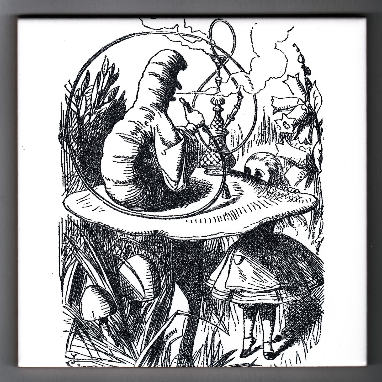
Now that you have a basic understanding of how HueFore works, let's practice using our sample image with your Snapmaker right away! The tutorial will be completed using the Snapmaker Artisan 3-in-1 3D Printer and the Dual Extrusion Model, while the process and steps are compatible with other Snapmaker printers.
You can use our recommended settings or make any adjustments to create your unique relief from it.
Step One: Create the Relief Design with Hueforge
- Download Hueforge.
You can purchase and download HueForge from its official website.
HueForge is compatible with Windows and MacOS 11+, and there are several pricing plans available for different usage needs.
- Download and import the sample image into HueForge.
Drag the file into the interface of HueForge or click File > Open File > Image in the top menu to import the image.
After the image is successfully imported, the relief preview (on the right) will be displayed next to the imported image.
By default, the preview consists only of black, grey, and white colors, which you can change in later steps.
HueForge supports images imported in the formats of PNG, JPG, JPEG, and WEBP.
If you want to create reliefs without a background, you should first remove the background from the original image using graphic processing applications like Photoshop before importing it into HueForge.
- Specify the parameters of the relief.
ⅰ. In the General Options and Operations panel, adjust the basic parameters of the relief.
Our recommended settings are shown in the picture (except for the width and height, which you can adjust according to your own needs).
ⅱ. In the Model Geometry panel, adjust the geometric parameters of the relief.
Our recommended settings are shown in the picture. We only modified the Min Depth to 0.48 and the Max Depth to 4.00, while you can also try experimenting with other parameters on your own.
- Select the filament used to print the relief.
On the Filament Library panel, drag the color icon of the selected filament to the slider in the Color Sliders panel. The colors we use are black, green, red, orange, yellow, and white.
If the filament you own is not listed in the default library, you can also add new filament and test
You can use filaments in the recommended colors above if they happen to be at your hand or use filaments in any other colors that you prefer and that are available around.
- Tweak the visual effect of the relief with the color sliders.
In the Color Sliders panel, move the sliders up and down to change the layering of filament.
Our recommended settings are shown in the picture (except for the TD values, which vary with filament and require additional testing for filament not listed in the default library).
High-TD white filament can be used as a smoother for color or brightness, generally placed between two colors that need to be smoothed.
- Generate the key information.
In the General Options and Operations panel, click Describe.
A window will pop up displaying key information needed for slicing: layer height, initial layer height, filament info, and most importantly, the filament swap instructions. You can either click to copy the information elsewhere convenient for later use, or click to generate it again when needed.
- Export the STL file.
In the top menu, click File > Export STL to export the STL file for slicing.
Step Two: Configure the Parameters with the Slicer
To demonstrate how to add the M600 command (for filament changing), we will use PrusaSlicer for slicing.
- Import the STL file and adjust the slicing parameters.
ⅰ. In PrusaSlicer, import the STL file, click Print Settings, and switch to the Advanced mode.
ⅱ. Adjust the parameters as specified below, as they are necessary for a successful relief print:
-
-
- Perimeters: 1
- Fill density: 100%
- Fill pattern: Rectilinear
- Top fill pattern: Monotonic Lines
- Bottom fill pattern: Monotonic Lines
- Detect thin walls: On
-
ⅲ. Check and make sure that the layer height and the first layer height set in the slicer are consistent with the Layer Height and Base Layer already set in HueForge.
ⅳ. Set the Black filament (or the "start with" filament described in the key information, as shown below) as the default filament for the model.
- Add the filament changing command (taking our HueForge configurations as an example).
ⅰ. Click Slice now. It might take a while for the G-code preview to display.
ⅱ. Along the layer bar on the right, find and click Layer 12 (1.16 mm).
ⅲ. Right click the plus sign that appears beside, click Add color change (M600) for: and select the Extruder 1 to add the filament changing command at that layer.
PrusaSlicer does not support the settings for the Dual Extruder Module. Therefore, you have to use one of the two extruders, which you choose to heat by operating on the Touchscreen, to print the entire relief.
ⅳ. Along the color selection window, change the color to Green.
ⅴ. Click Slice now to save the added command.
In the following steps, each time after you add the command and change the color, be sure to click Slice now to save the settings.
ⅵ. Along the layer bar on the right, find and click Layer 16 (1.48 mm).
ⅶ. Add the M600 command and change the color to Red.
ⅷ. Along the layer bar on the right, find and click Layer 25 (2.2 mm).
ⅸ. Add the M600 command and change the color to Orange.
ⅹ. Along the layer bar on the right, find and click Layer 33 (2.84 mm).
xi. Add the M600 command and change the color to Yellow.
xii. Along the layers bar on the right, find and click Layer 38 (3.24 mm).
xiii. Add the M600 command and change the color to White.
In this way, the printing will pause at the layer where the M600 command is added so that you can manually change the filament.
- Double-check all the settings.
ⅰ. Check if the key slicing parameters are specified as required.
The commands you have added will be saved even if you switch to the Print Settings tab.
ⅱ. Click Slice now again.
ⅲ. In HueForge, click Normal in the General Options and Operations panel to switch to the slicer preview mode, and check if the preview looks the same (or almost the same) as the G-code preview in the slicer.
- Export the G-code to the printer and start printing.
- Manually change the filament when the printing pauses as configured.
ⅰ. After the printing pauses at a specific layer, tap on the Touchscreen to set the temperature of the working nozzle to 200℃.
ⅱ. After the nozzle is heated up to 200℃, manually unload the filament.
-
-
- Open the front cover of the toolhead.
- Press the extruder buckle downwards to expand the dual-gear extruder.
- Pull the filament out of the toolhead.
-
You may need to use a little force or heat the nozzle to a slightly higher temperature to assist the unloading.
ⅲ. Manually load the new filament.
-
-
- Insert the filament into the toolhead until it is pushed right into the feed hole of the hot end and is extruded from the nozzle.
- Gently push the filament down until the old filament is completely extruded out and the new filament runs out smoothly.
- Press the extruder buckle back in place and close the front cover.
-
ⅳ. On the Touchscreen, tap to resume printing.
ⅴ. Repeat the above steps each time when the printing pauses as configured.
How to Test the TD Value of Filament
Testing the TD value of the filament used to print the relief is very important, as it relates to whether the relief preview you see in the HueForge matches the actual printing result. You can take the following steps to conduct the test.
- In the local directory of HueForge, locate the Step_Test_Sqaure.stl file in the Tools folder and import it into HueForge. The interface should display as below.
- In the Color Sliders panel, adjust the first four sliders to match the ones displayed in the picture.
- At the bottom of the Filament Library panel, click New Filament to add the filament you want to test.
- Take a photo of the filament in a well-lit environment and use the eyedropper tool to extract the color of the filament from the photo.
- In the Add Filament window, specify the necessary information about the filament. You can keep the TD value at its default setting for now, as it won't have any impact on the testing result.
- Click and drag the color icon of the newly added filament into the second slider to replace the default grey color.
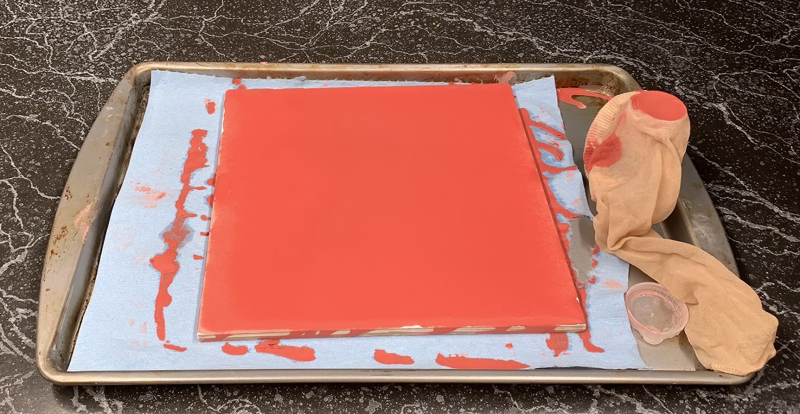
- Export the STL file, configure the settings in the slicer, and print the model out.
- In HueForge, adjust the TD value of the tested filament in the Color Sliders panel until the relief preview looks as close as possible to the print.
Useful Tips for Large Prints
For large-sized prints, you can increase the success rate of printing by following these tips:
- Adjust the first layer height appropriately. For example, when printing objects with a horizontal or vertical size of 300 or 400 mm, you can set the layer height as 0.2-0.28 mm (just for reference).
- Turn off the part cooling fan during printing.
- Preheat the heated bed to the target temperature for 15-20 minutes before printing to stabilize the bed deformation. It is also recommended to raise the bed temperature appropriately (to 70-75°C, for instance).
- Wait until the first layer is printed successfully before leaving, as it can take some time to read the file before printing, during which the temperatures of the nozzle and heated bed may decrease.
- Adjust the height of the working nozzle as necessary to enhance the first layer printing result.
- If there are strings on the print, you can reduce the nozzle temperature by 5-10℃ to improve the print quality.
- If you are using Snapmaker Artisan:
- After preheating, calibrate the Z offset of the left and right nozzle, and use the right nozzle to calibrate the heated bed (either at 25 or 81 points).
- When heating and loading the nozzle, make sure to heat the heated bed simultaneously to avoid sudden drops in the bed temperature.
- Use the glass side of the build plate and apply printing adhesives.
Learn more about Snapmaker Artisan 3-in-1 3D Printer.


