Laser Engraving and Cutting
1 Set Up for First Use
Read the product Quick Start Guide to check the included parts, assemble the machine, and set up the machine for the first use. You can also watch the video tutorials on our website to learn how to use the machine.
2 Two Methods to Start Engraving and Cutting
There are two methods to start laser engraving and cutting: setting work origin or using the Camera Capture feature.
2.1 Setting Work Origin
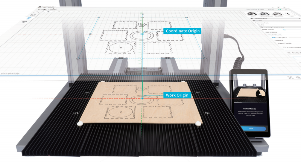
You need to find out where the engraving and cutting will be by setting the work origin. The work origin corresponds to the (0, 0) coordinate origin in the software Snapmaker Luban.
Here is the workflow of this method.
Measure Focal Length
⬇
Fix Material to Platform
⬇
Prepare File
⬇
Generate G-code
⬇
Transfer G-code File to Machine
⬇
Set Material Thickness
⬇
Set Work Origin and Run Boundary
⬇
Start Engraving and Cutting
Note 1: Ensure that you have worn the Laser Safety Goggles before proceeding.
Note 2: If the focal length is already measured, skip Measure Focal Length.
Note 3: For detailed instructions on how to Transfer G-code File to Machine, see 5 Transfer G-code File to Machine.
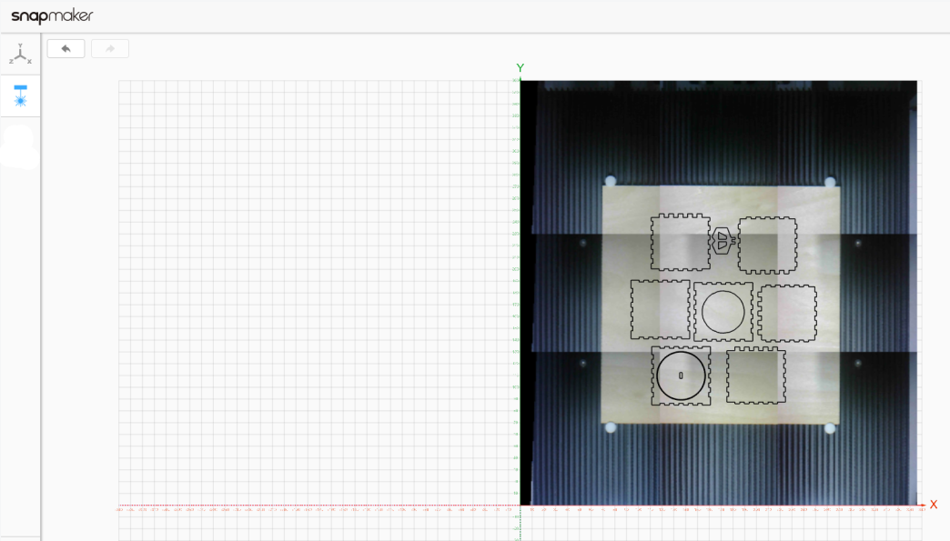
2.2 The Method of Using Camera Capture Feature
The laser module's camera captures photos of the work area, and stitch them together as the background. You don't need to set the work origin, and just drag the laser model to where the engraving and cutting will be on the captured background. For detailed instructions on how to use the Camera Capture feature, see Quick Start Guide.
Here is the workflow of this method.
Measure Focal Length
⬇
Calibrate Camera
⬇
Fix Material to Platform
⬇
Connect Computer to Machine via Wi-Fi
⬇
Captures Background of Work Area
⬇
Prepare Files
⬇
Upload and Drag Image to the Captured Background
⬇
Generate G-code
⬇
Load G-code to Workspace
⬇
Set Material Thickness
⬇
Start Engraving / Cutting
3 Prepare Files
Design: You can draw with a pen, design a 2D image with graphic design software such as Inkscape and Adobe Illustrator, or simply select a picture from your smartphone.
Take a Photo: You can get a 2D image of scenes or objects in real life by taking a photo with your smartphone.
Download: You can find various beautiful images online from websites like pinterest.com and vectorstock.com.

4 Generate G-Code
This manual uses Luban version 3.15.1 to demonstrate how to generate the G-code file.
4.1 Generating G-code Workflow
Here are the steps:
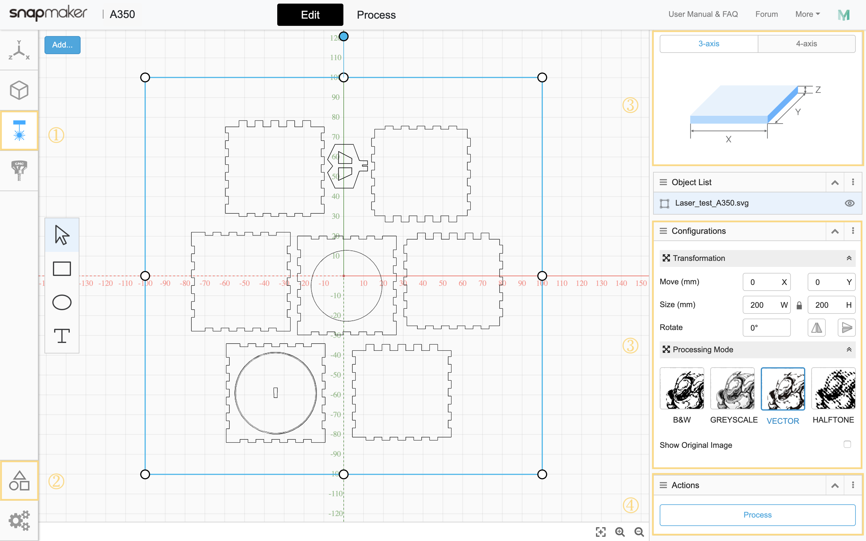
① In the left bar, select Laser G-code Generator![]() .
.
② Go to Case Library and Load the provided 3-axis laser model (Laser Cut Gift Box) to canvas.
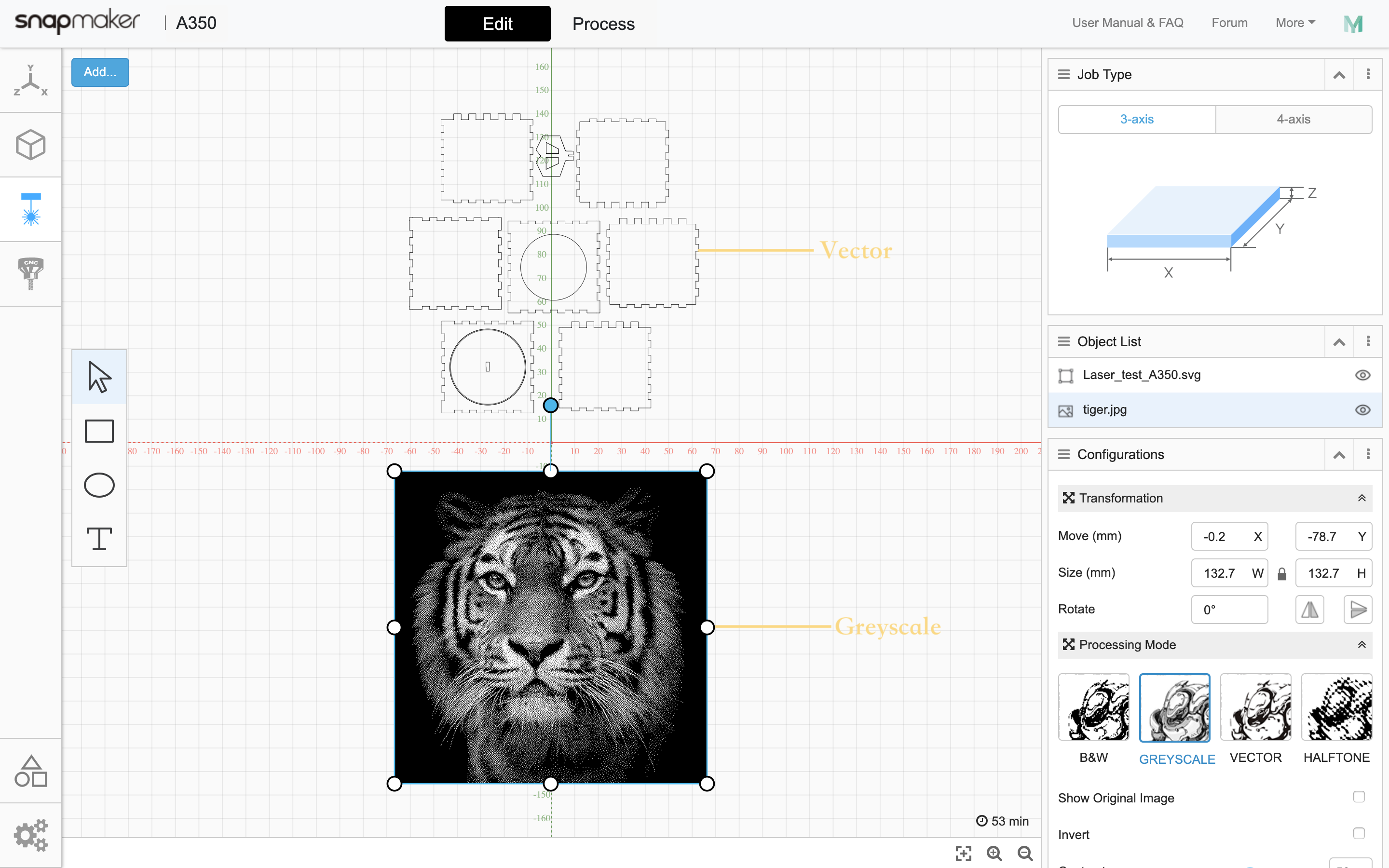
③ In Job Type, select 3-axis. In Configurations, set transformation parameters and select a processing mode.
Note 1: The laser model size should be smaller than our provided material size (200 × 200 mm).
Note 2: For detailed parameter instructions, see The Definitive Guide to Laser Engraving and Cutting with the Snapmaker.
④ In Actions, click Process.
Now Luban jumps to the Process interface where you can create and preview toolpath.
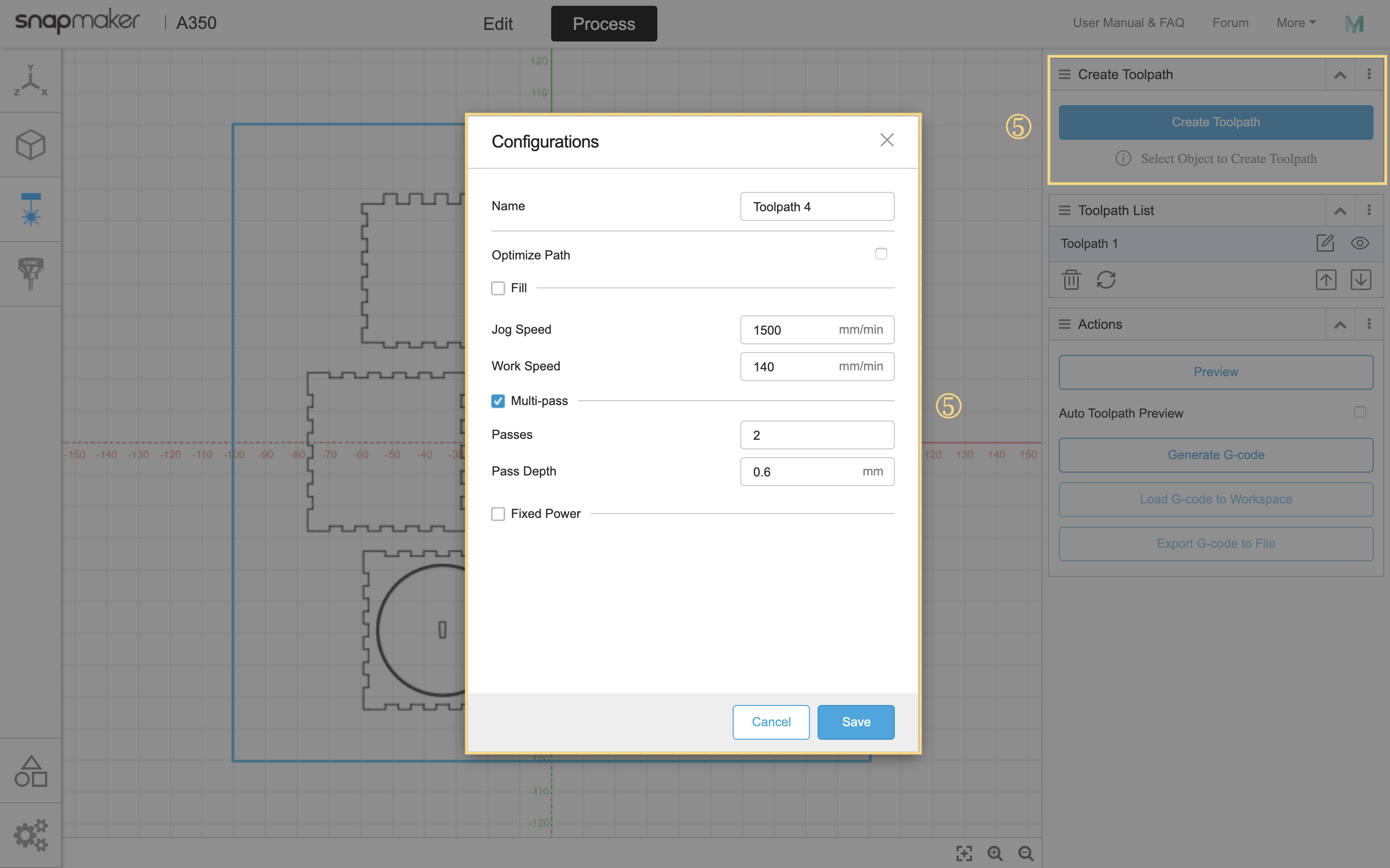
⑤ Select the model and click Create Toolpath. In the pop-up Configurations panel, set cutting parameters and click Save.
Note: the provided laser model in Luban already has toolpath, you can skip this step and click the Edit![]() button in Toolpath List to check the parameters.
button in Toolpath List to check the parameters.
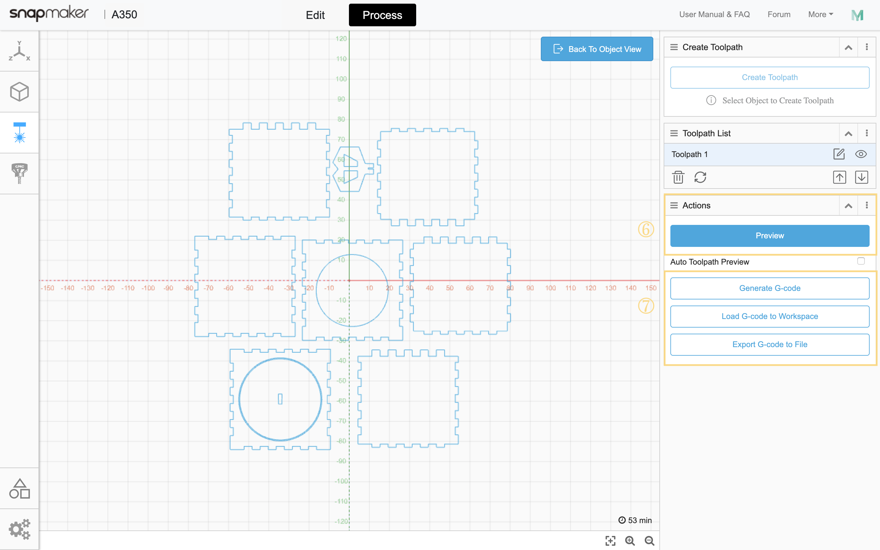
⑥ In Actions, click Preview to preview the toolpath. To switch to the object view where you can create toolpath, click Back to Object View in the top right corner of the canvas.
⑦ Click Generate G-code.
Tip: Before setting parameters, left-click the model to select it. To see the context menu, right-click the model.
4.2 Engraving and Cutting Mode
4.2.1 Engraving Mode
B&W, Greyscale, Vector, and Halftone can all be used for engraving.
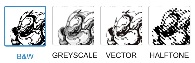
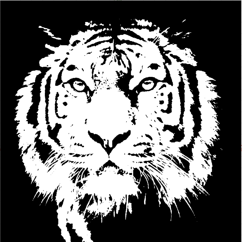
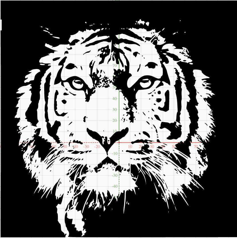
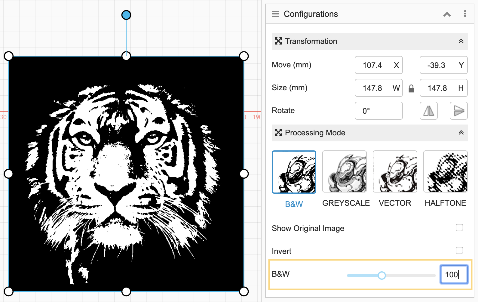
B&W: The engraved image will be in black and white without any grey color.
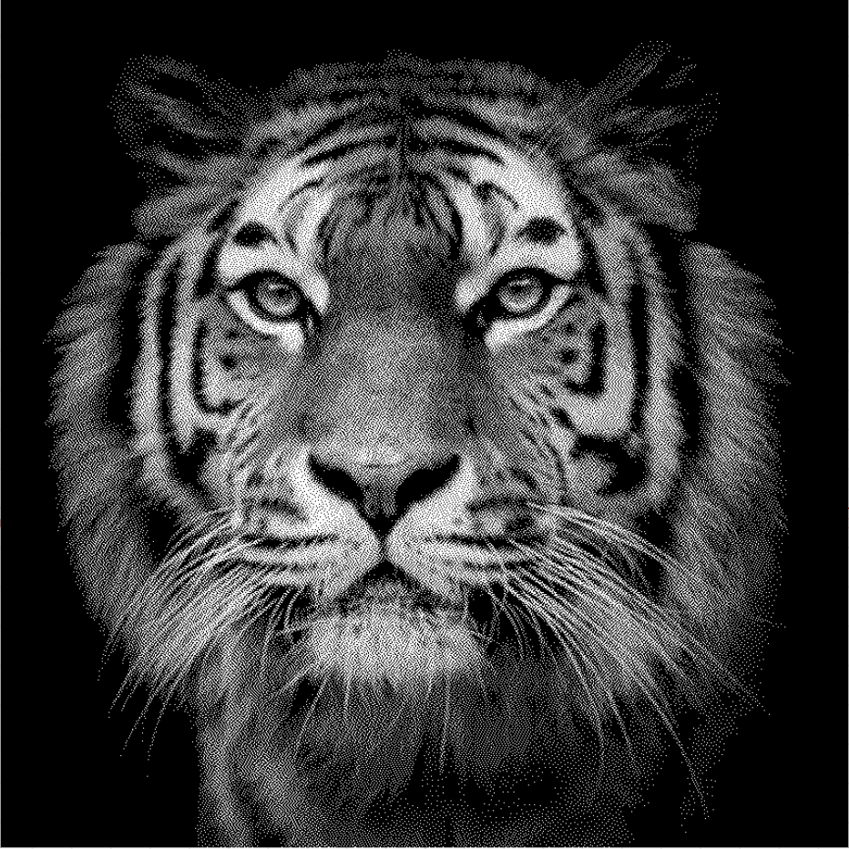
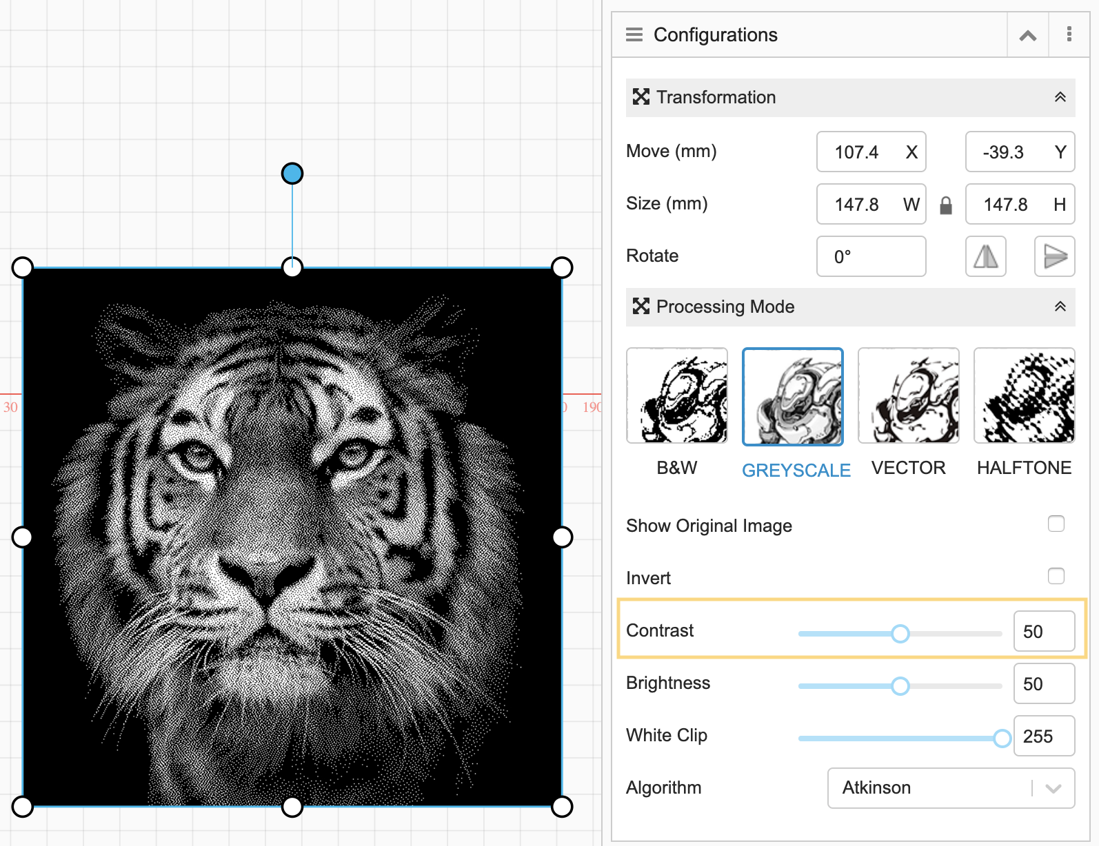
Greyscale: The engraved image will be in different shades of grey depending on its original color.
Vector: This effect is used for engraving vector graphics. The engraved image will be in black and white without any grey color.
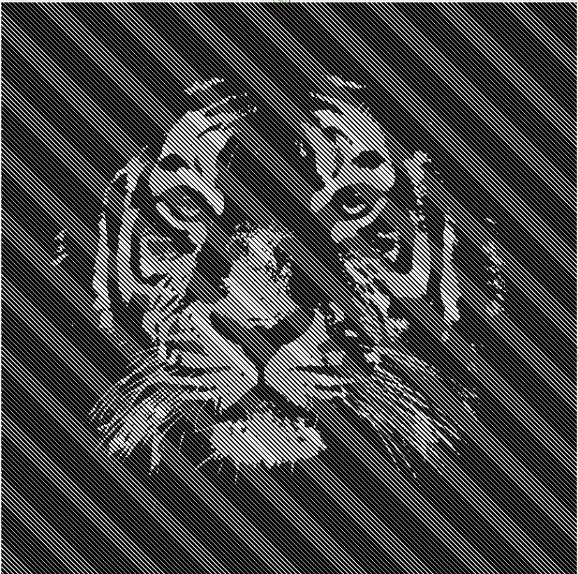
Halftone: This effect simulates continuous-tone imagery through the use of dots, varying in size or spacing, thus generating a gradient-like effect.
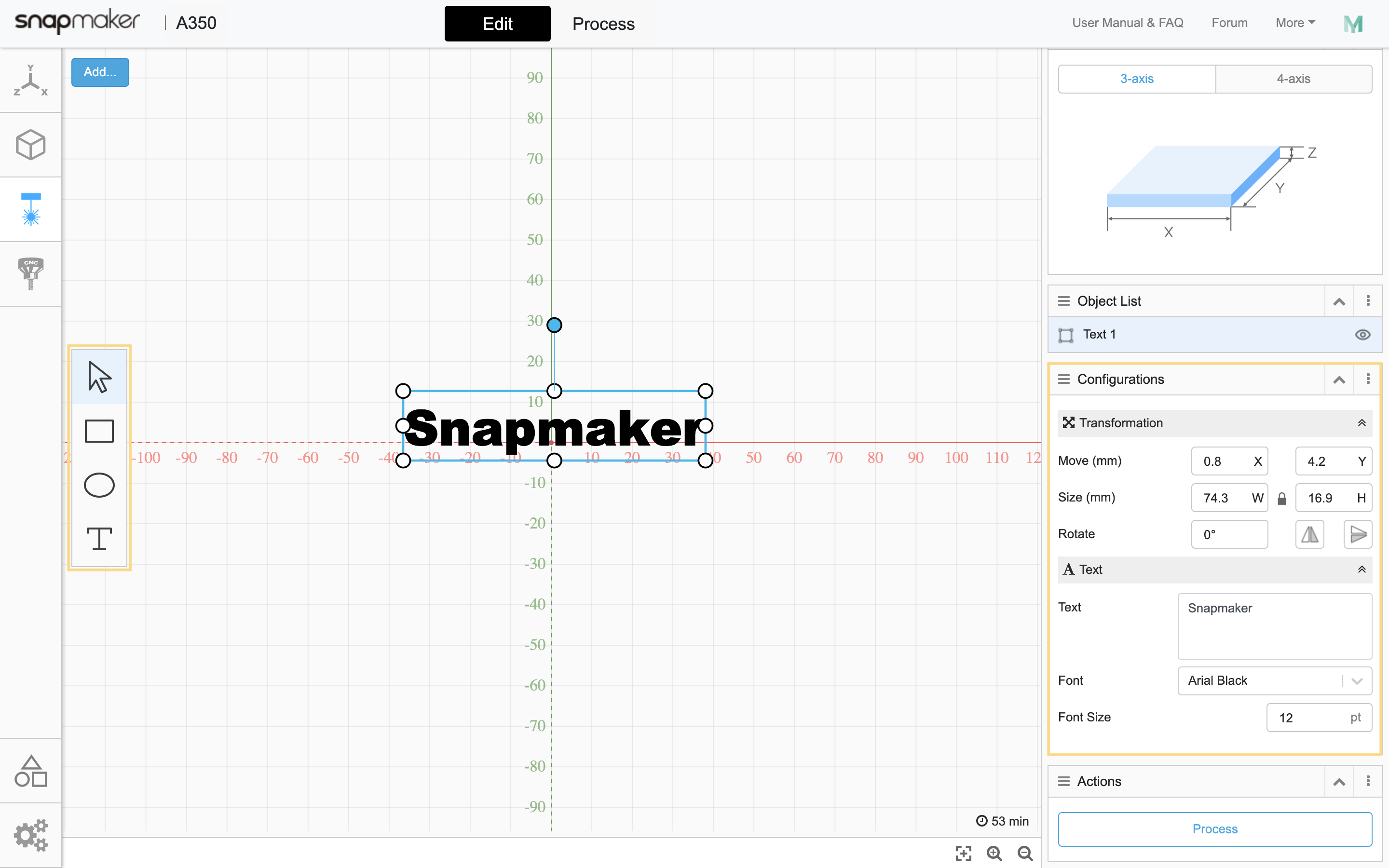
Text: You can enter text, select the font and size, and edit its transformation parameters as you need.
4.2.2 Cutting Mode
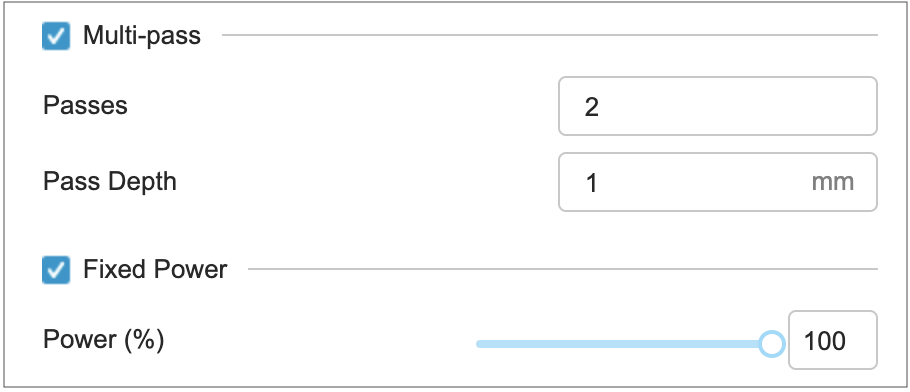
The Vector and Text modes both can be used for engraving and cutting. When laser cutting, you can set the Multi-pass and Fixed Power settings to a desirable level based on the materials you use.
4.3 Multi-model Engraving and Cutting
You can upload multiple files to different modes to engrave / cut them in the same G-code file. For instance, if you have used the Vector mode to upload a SVG file for cutting, you can also use the Greyscale mode for engraving with a JPG file. You only need to set different parameters for individual images to be able to engrave and cut simultaneously.
 Note 1: When multiple images overlap, right-click the images to Bring to Front and Send to Back to arrange the image position.
Note 2: To engrave and cut in the same area, we recommend that you engrave first to avoid any loss of engraving quality when the materials become less stable after being cut. You can set the work order by going to Print Order.
4.4 Parameters in B&W Mode
Some parameters in B&W mode are listed below to help you familiarize with their meanings. You can learn about all the parameters by reading the prompts, which will appear when you hover your cursor over the tags in our software.
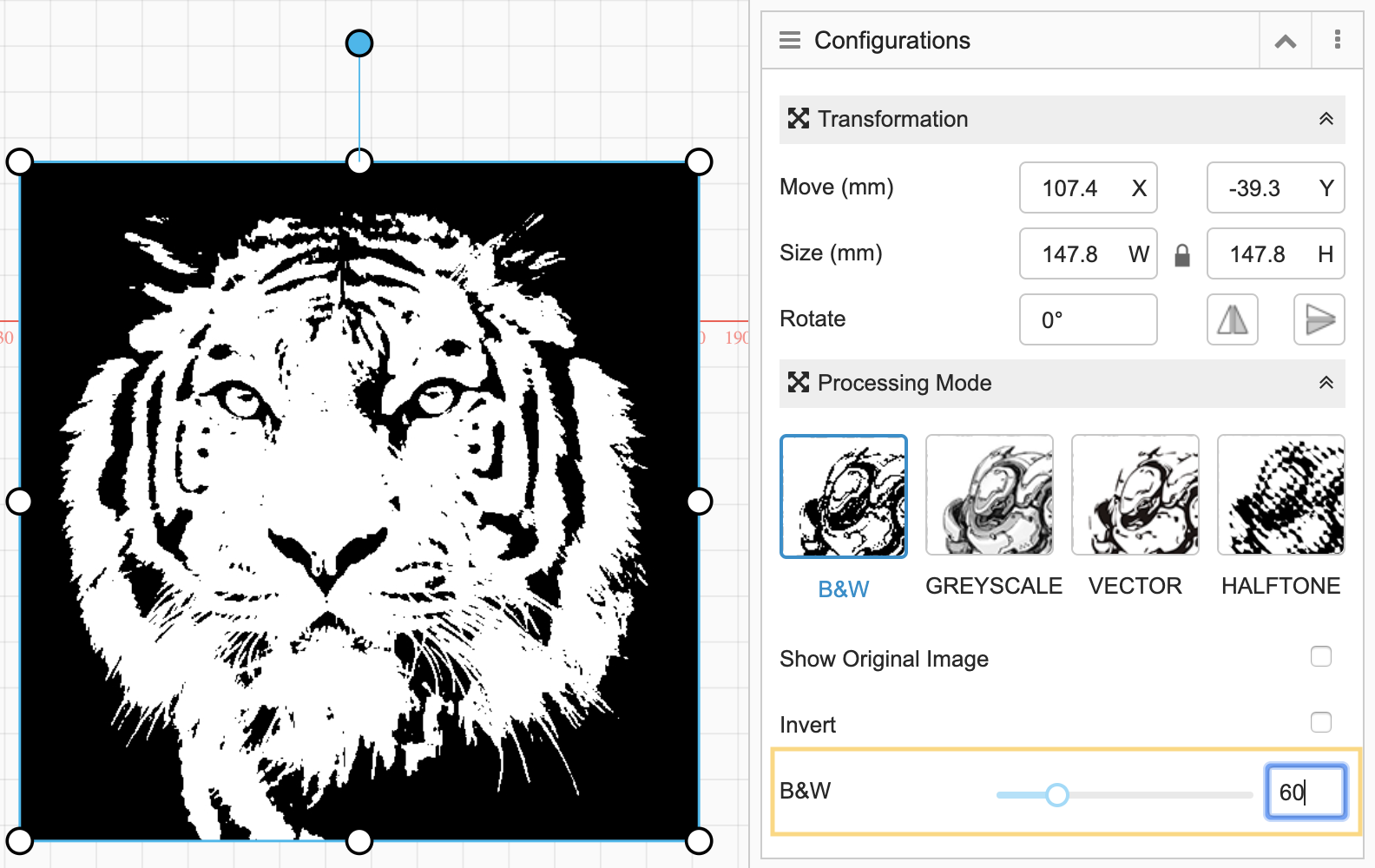
Invert: Inverts black to white and vise versa.
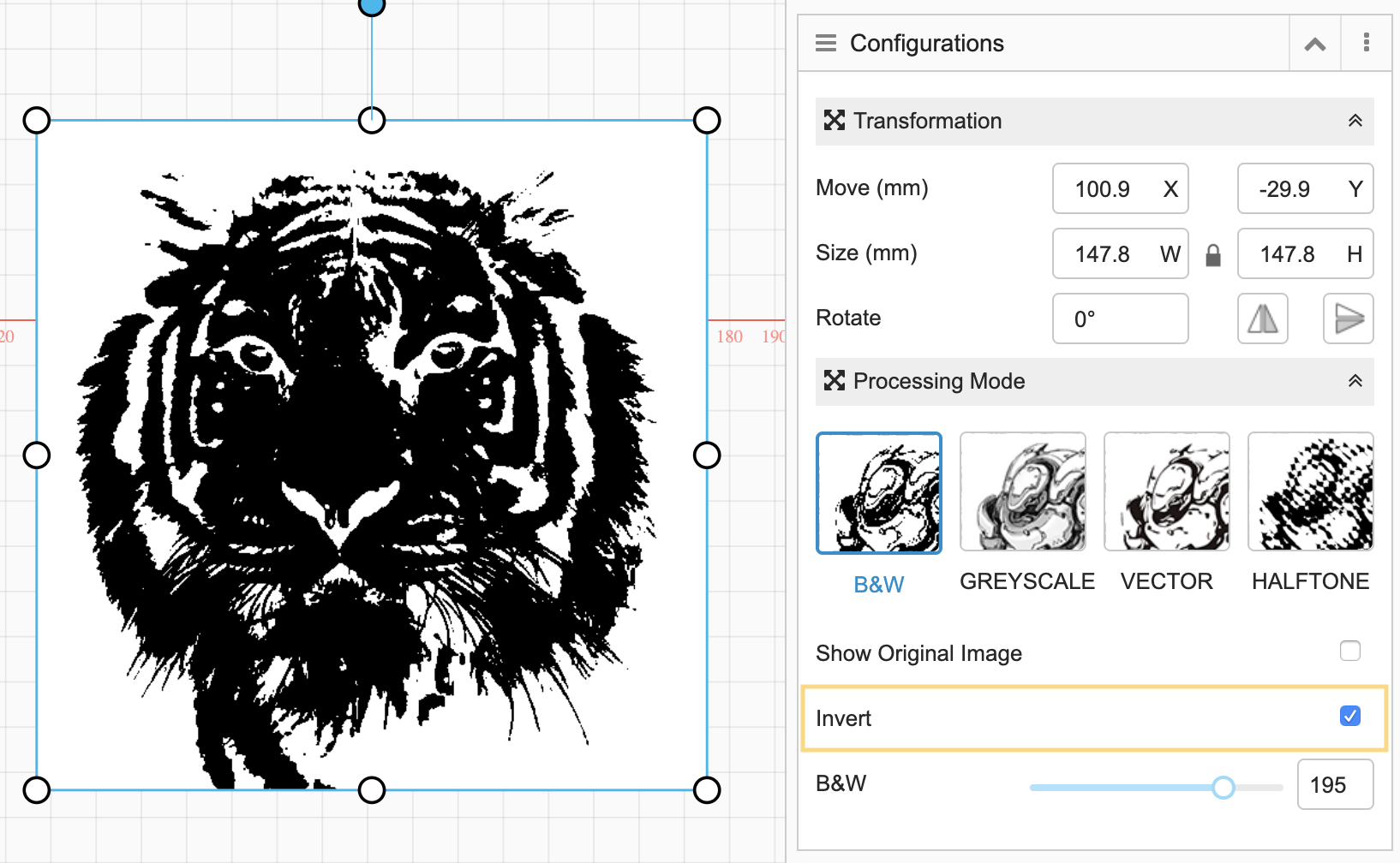
B&W: Set the proportion of the black color based on the original color of the image. The bigger this value is, the bigger the proportion of the black color will be.
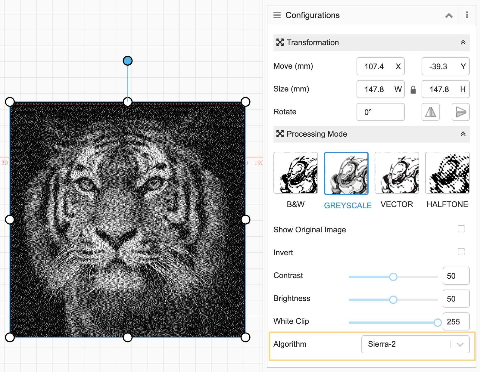
4.5 Parameters in Greyscale Mode
Some parameters in Greyscale mode are listed below to help you familiarize with their meanings. You can learn about all the parameters by reading the prompts, which will appear when you hover your cursor over the tags in our software.
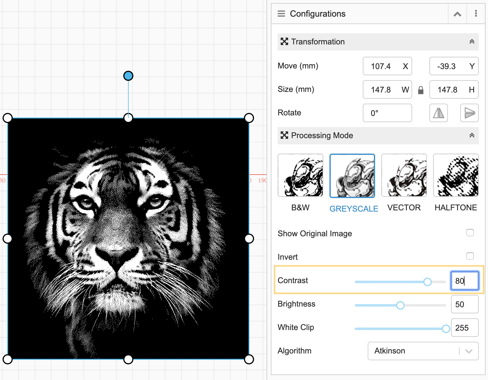
Contrast: The difference between the lightest color and the darkest color. The contrast is more obvious when this value is bigger.
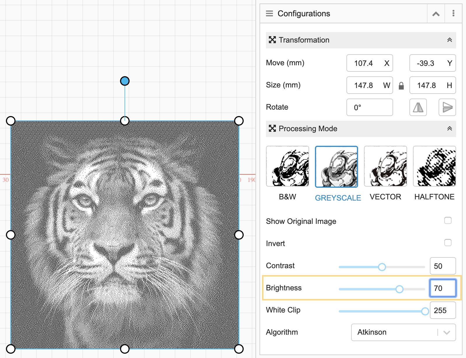
Brightness: The engraved picture is brighter when this value is bigger.
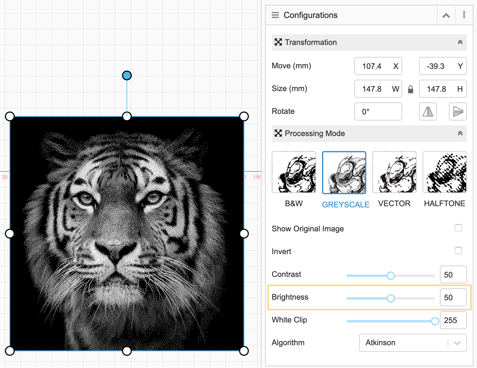
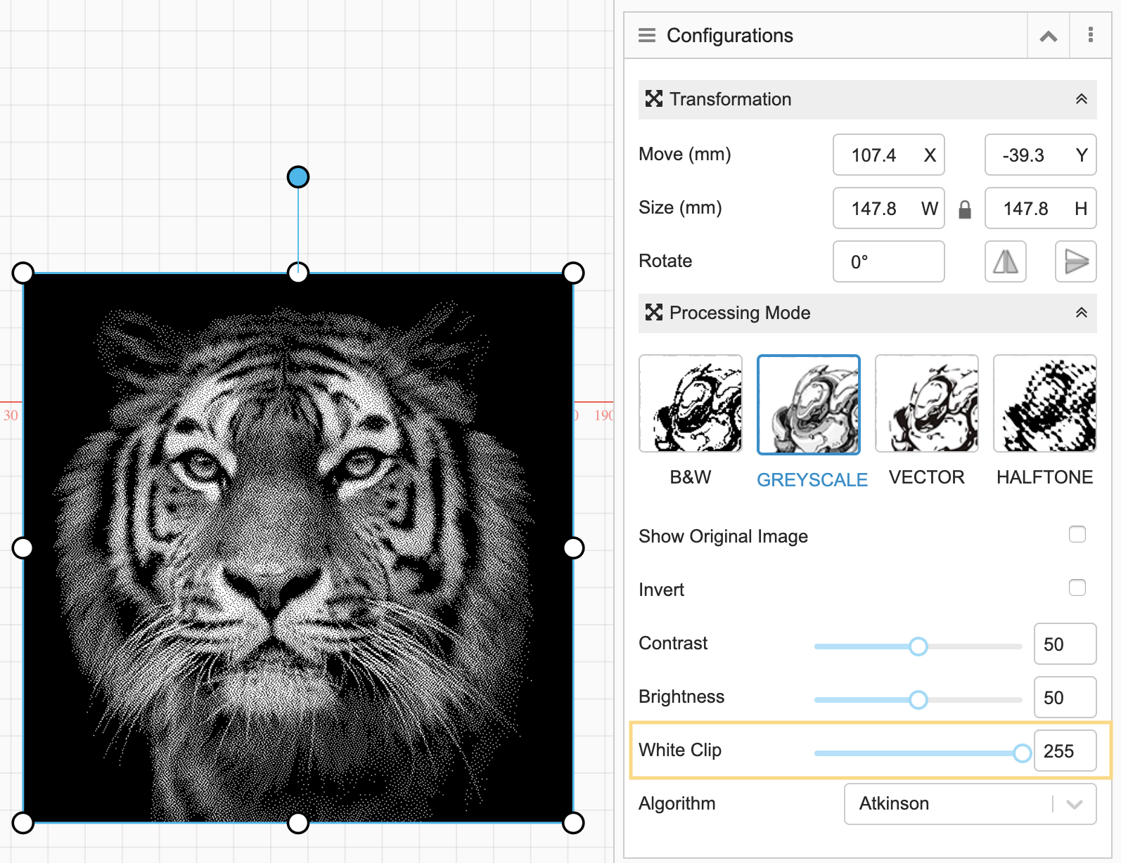
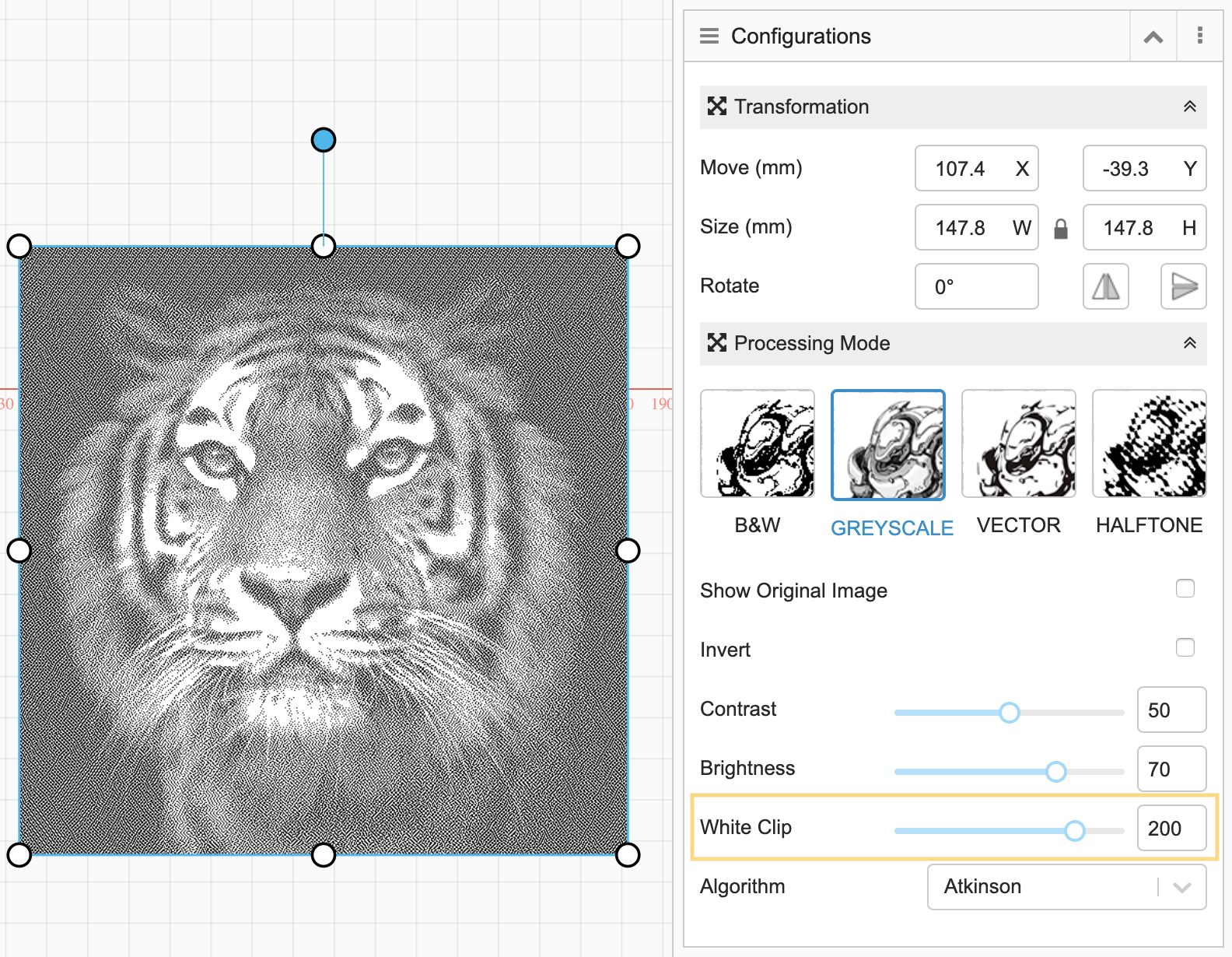
White Clip: Set the threshold to turn the color that is not pure white into pure white. 0 means pure black and 255 means pure white and each of the colors in between is assigned a specific number. If White Clip is set to 88, colors whose number is larger than 88 will be turned into pure white (255).
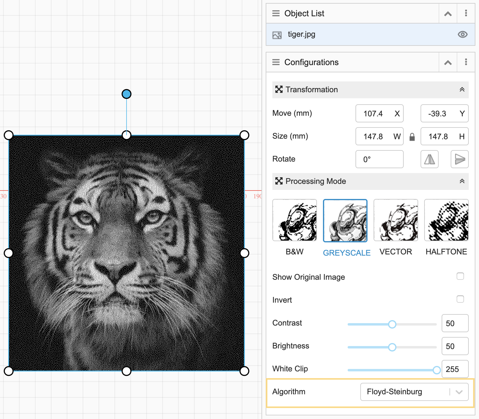
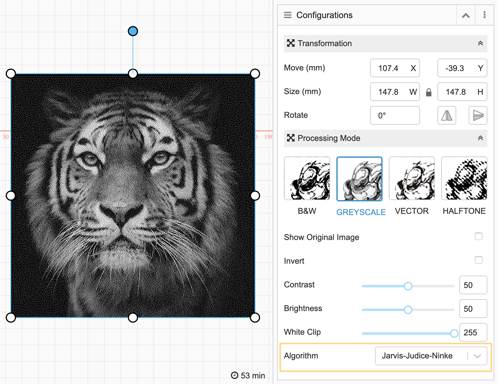
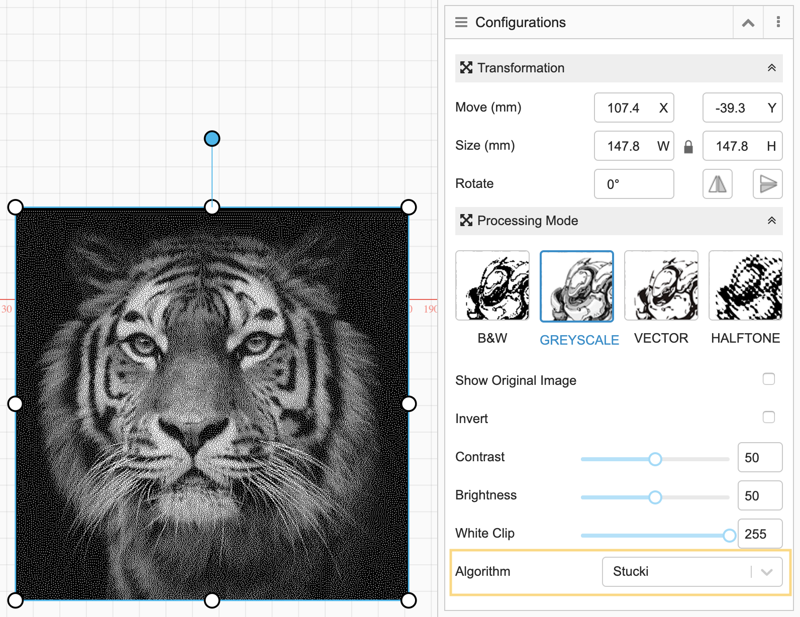
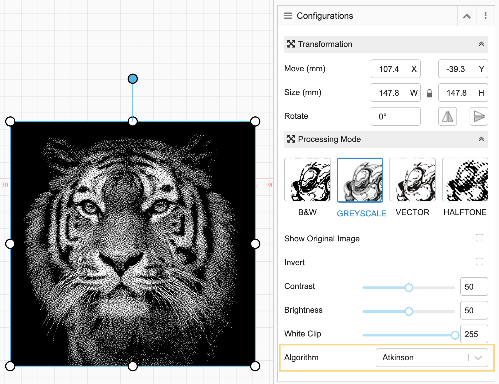
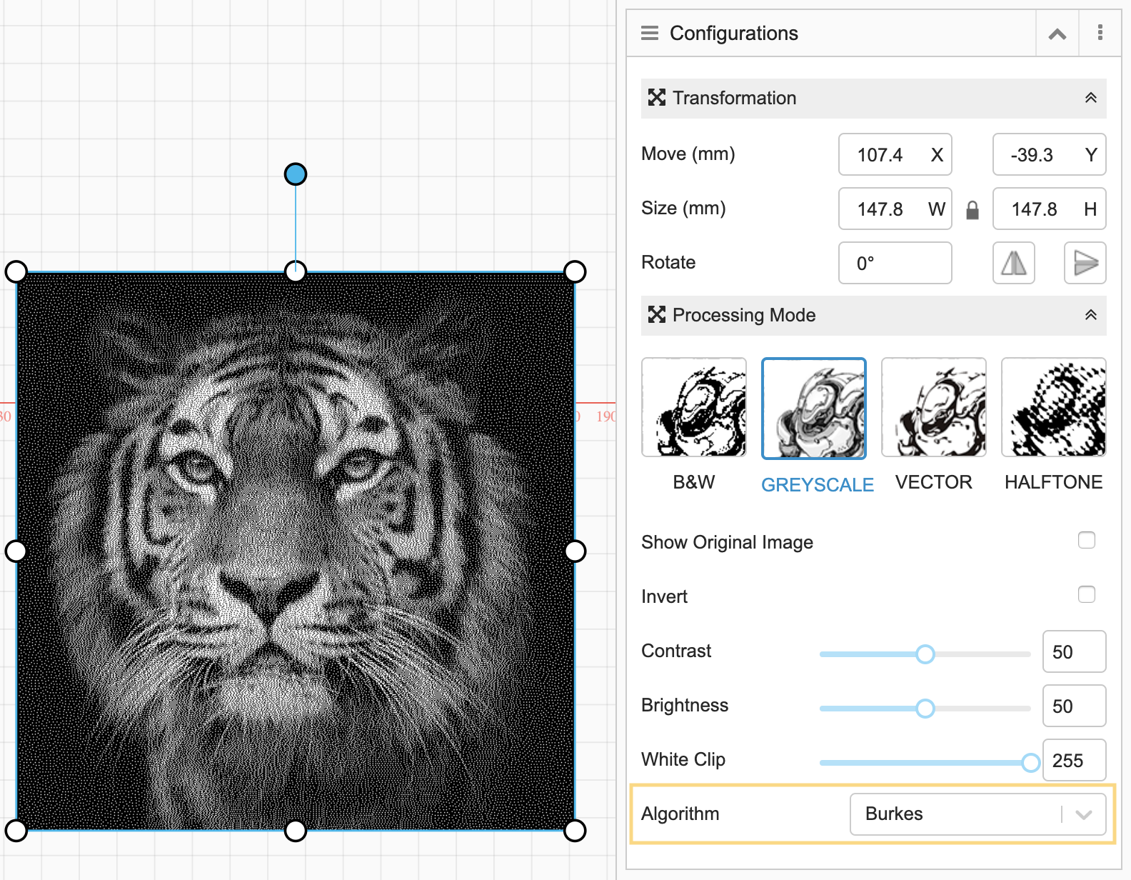
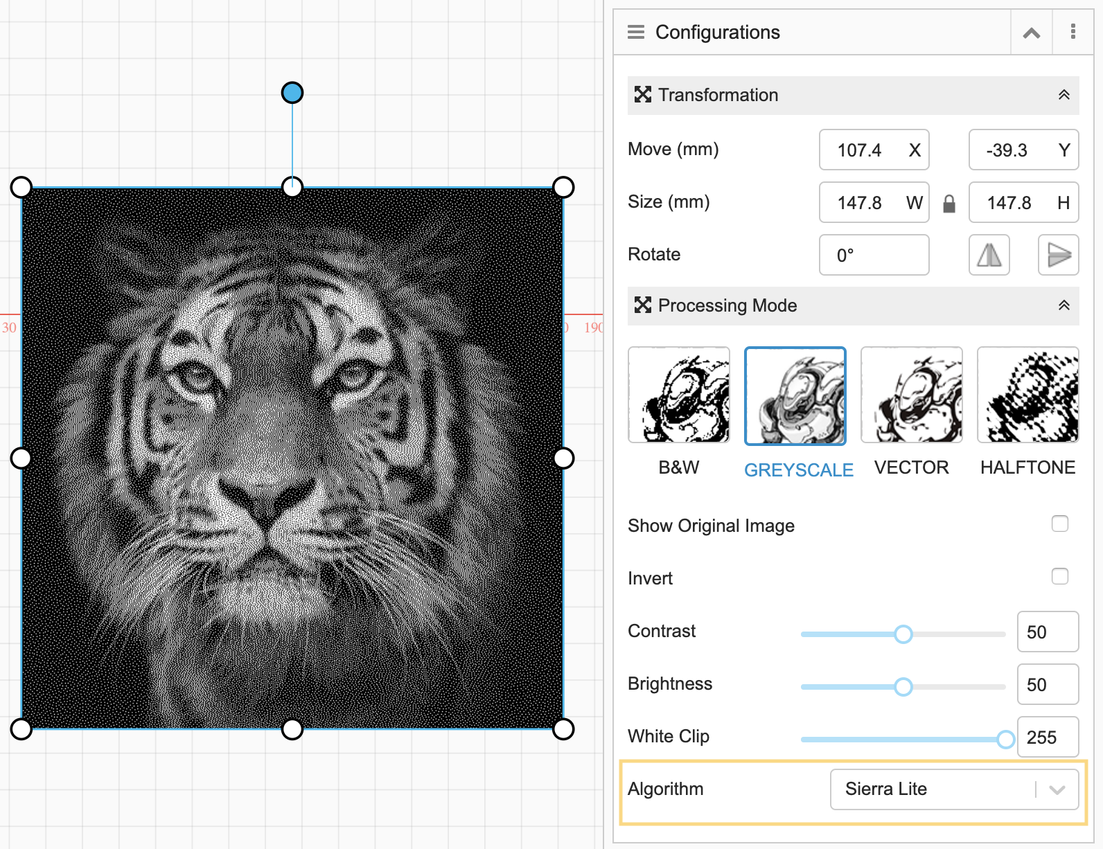
Algorithm: Choose an algorithm for image processing. See the effect of different Algorithms below.
Floyd-Steinburg:
Jarvis-Judice-Ninke:
Stucki:
Atkinson:
Burkes:
Sierra-2:
Sierra-3:

Sierra Lite:
5 Transfer G-code File to Machine
5.1 Online Engraving / Cutting
5.1.1 Transfer G-code File via Wi-Fi
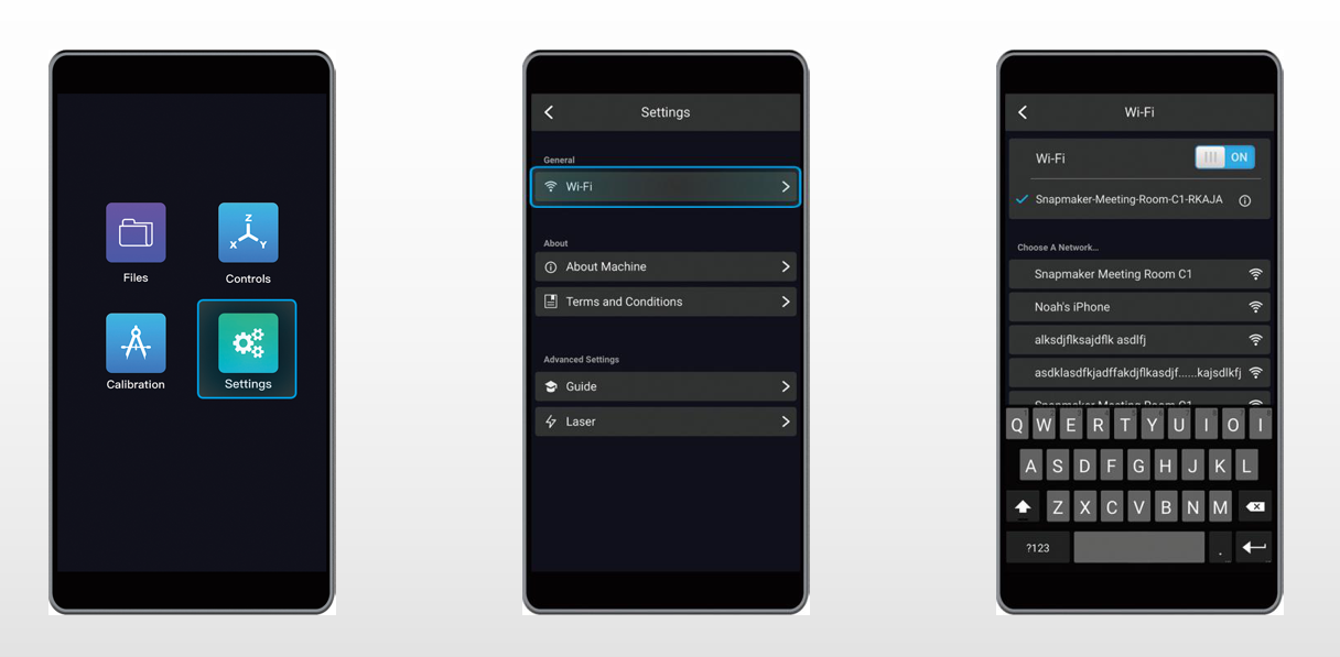
1. If the machine is not yet connected to Wi-Fi, select Settings in the main menu, tap Wi-Fi and connect to your network.
2. Before you connect your computer to the machine, ensure that the computer and the machine have connected to a same Wi-Fi network. Open Snapmaker Luban and go to Workspace![]() -> Connection -> Select Wi-Fi -> Click
-> Connection -> Select Wi-Fi -> Click -> Select your device -> Click Open -> Tap Yes on the touchscreen.
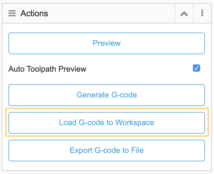
3. Go to Laser G-code Generator![]() and select Load G-code to Workspace to load the generated G-code to Workspace.
and select Load G-code to Workspace to load the generated G-code to Workspace.
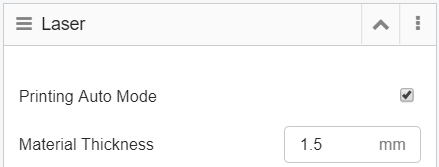
4. If you have already measured the focal length and material thickness, enter the thickness in Printing Auto Mode.
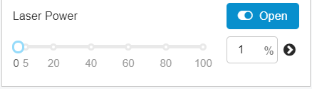
5. Set a relatively small value (e.g. 1%) for Laser Power and turn on the laser beam.
6. Use X- / X+ / Y- / Y+ / Z- / Z+ to move the laser dot to where the work origin will be, click Set Work Origin and Run Boundary to check if the work origin is at the right place.
Note: If the work origin is set up incorrectly, reset the work origin and run boundary again.
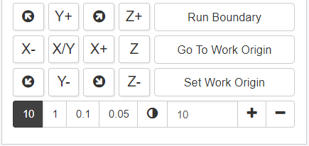
7. Click Run ![]() to start engraving / cutting.
to start engraving / cutting.
Note 1: The computer must be connected to the machine via Wi-Fi throughout the process.
Note 2: You can change the settings for Laser Power and Work Speed during the engraving / cutting process.
Tip: If the material thickness is unknown, you can deselect Printing Auto Mode and change to Printing Manual Mode.
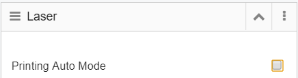
When using the Printing Manual Mode, do the following:
Set a relatively small value (e.g. 1%) for Laser Power and turn on the laser beam -> Use X- / X+ / Y- / Y+ / Z- / Z+ to move the laser dot to where the work origin will be -> Use Z- / Z+ to adjust the height of the laser module until the laser beam is focused down to the smallest spot -> Click Set Work Origin -> Click Run Boundary -> Click Run ![]() to start engraving / cutting.
to start engraving / cutting.
Note: If the work origin is set up incorrectly, reset the work origin and run boundary again.
5.2 Offline Engraving and Cutting
5.2.1 Transfer G-code File via Wi-Fi
1. If the machine is not yet connected to Wi-Fi, select Settings in the main menu, tap Wi-Fi and connect to your network.

2. Before you connect your computer to the machine, make sure both the computer and the machine have connected to the same Wi-Fi. Open Snapmaker Luban and go to Workspace -> Connection -> Select Wi-Fi -> Click
 -> Select your device -> Click Open -> Tap Yes on the touchscreen.
3. Go to Laser G-code Generator and select Load G-code to Workspace to load the generated G-code to Workspace.
4. Go to Workspace and click Send to Device via Wi-Fi.
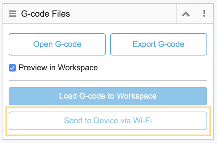
5. After the machine has received the G-code file, tap Yes on the touchscreen to access the preview page for engraving / cutting.
Note 1: To learn more about the Auto Mode and Manual Mode before you start engraving / cutting, see section 6.1 Auto mode and Manual Mode.
Note 2: Files sent via Wi-Fi are in the Files -> Local on the touchscreen.
5.2.2 Transfer G-code File via USB flash drive
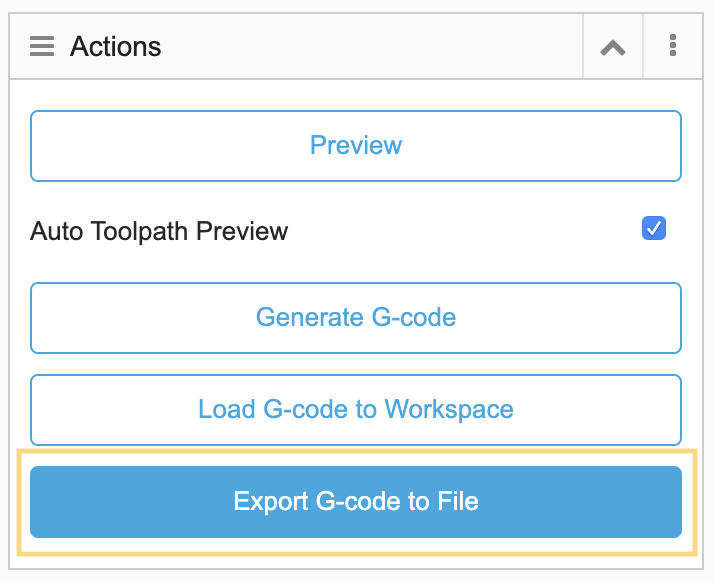
1. Go to Laser G-code Generator![]() and click Export G-code to File to save the file to your flash drive.
and click Export G-code to File to save the file to your flash drive.
Note: To save G-code as a usable file, the file extension has to be ".nc".
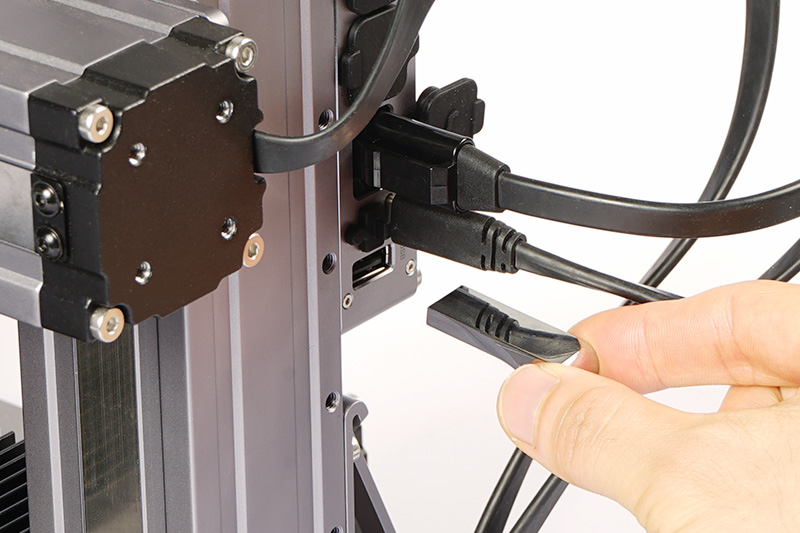
2. Plug in your USB flash drive to the controller of the machine.
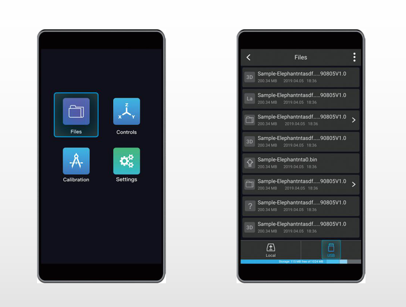
3. Tap Files in the main menu -> USB, locate the saved G-code file to start engraving / cutting.
Note: To learn more about the Auto Mode and Manual Mode before you start engraving / cutting, you can go to section 6.1 Auto mode and Manual Mode.
6 Common Operations
6.1 Auto Mode and Manual Mode
You can start engraving / cutting by selecting either the Auto Mode or Manual Mode after you tap Next on the preview page using the touchscreen.
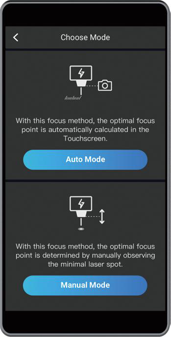
1. Auto Mode
If you have measured the focal length and know the material thickness, you can follow the steps in Auto Mode: Enter the material thickness -> Use X- / X+ / Y- / Y+ to move the laser beam to where the work origin will be -> Tap Set Work Origin -> Tap Run Boundary -> Tap Start to start engraving / cutting.
Note: If the work origin is set up incorrectly, reset the work origin and run boundary again.
2. Manual Mode
If the material thickness is unknown, you can do the following in Manual Mode: Use X- / X+ / Y- / Y+ / Z- / Z+ to move the laser dot to where the work origin will be -> Use Z- / Z+ to adjust the height of the laser module until the laser beam is focused down to the smallest spot -> Tap Set Work Origin -> Tap Run Boundary -> Tap Start to start engraving / cutting.
Note: If the work origin is set up incorrectly, reset the work origin and run boundary again.
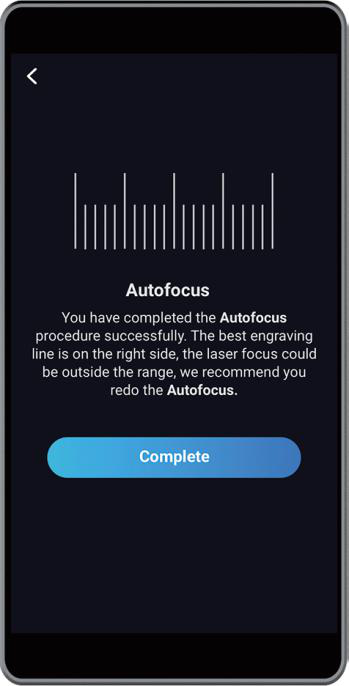
6.2 Remeasure Focal Length
If you are using Autofocus to measure the focal length, you need to remeasure the focal length under these two circumstances:
Note: You should tap Complete and select Calibration to measure the focal length after loading into the main menu. Do not click Back  to repeat the step.
1. If the machine recognizes the one of the lines on the right as the optimal engraved line, the touchscreen will notify that you should remeasure the focal length.
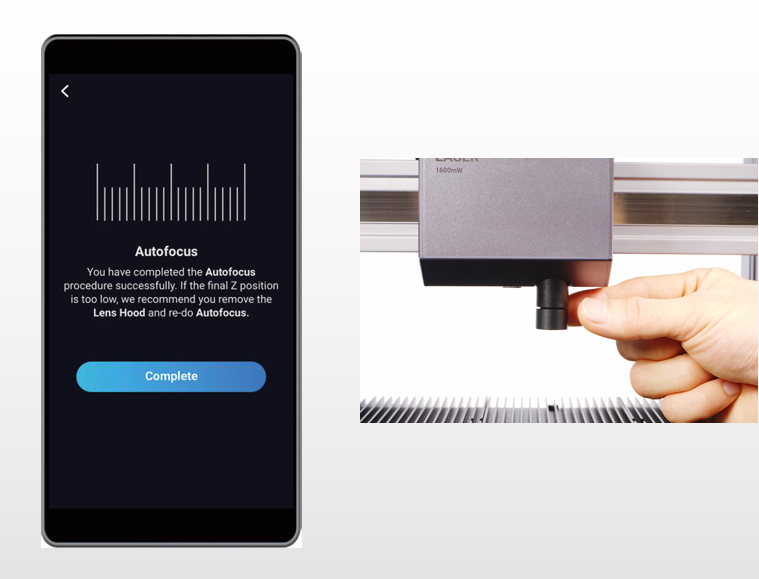
2. If the machine recognizes one of the lines on the left as the optimal engraved line, the touchscreen will notify that you should remeasure the focal length. And that you should take off the lens hood before remeasuring the focal length.
Warning: Do not reinstall the lens hood after measuring the focal length, otherwise the lens hood will run into the materials during the engraving / cutting process.
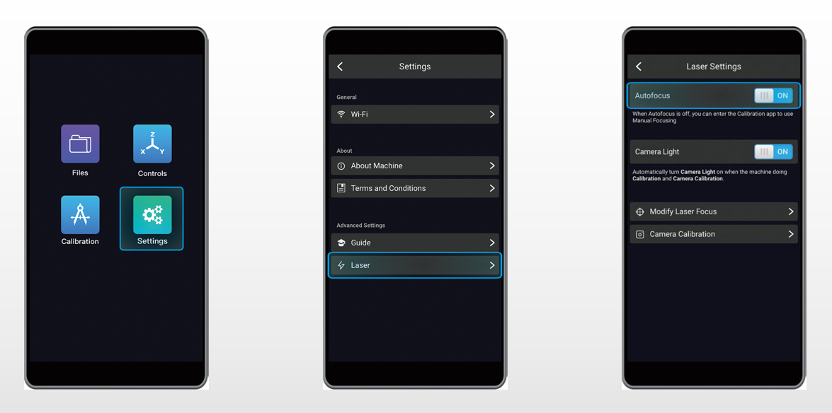
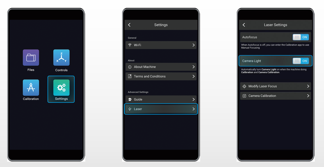
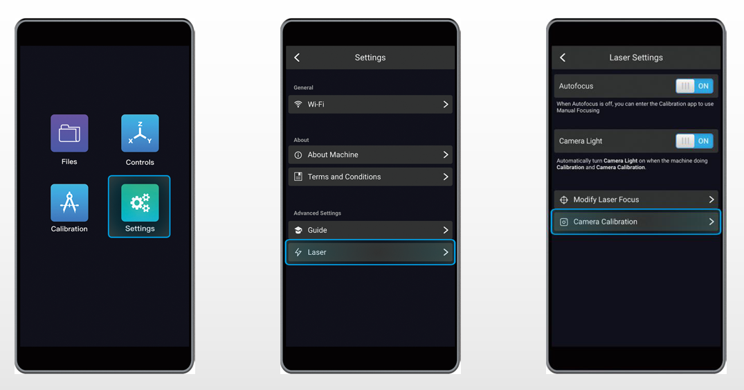
6.3 Manual Focusing
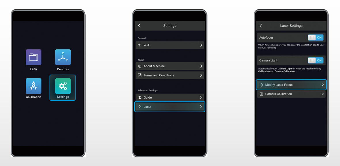
Autofocus is enabled by default when you tap Calibration in the main menu when measuring the focal length. If the camera does not work properly, you can switch to Manual Focusing to measure the focal length: Tap Settings in the main menu -> Tap Laser -> Turn off Autofocus to switch to Manual Focusing under the Laser Settings.
6.4 Modify Laser Focus
If you want to change the focal length, you can select Settings and then Laser -> Modify Laser Focus.
6.5 Adjust Lens Hood
During the laser engraving / cutting process, if you feel that the lens hood is too far from the surface of the material to have the best light-blocking effect, you can follow the steps below to adjust the settings for the lens hood:
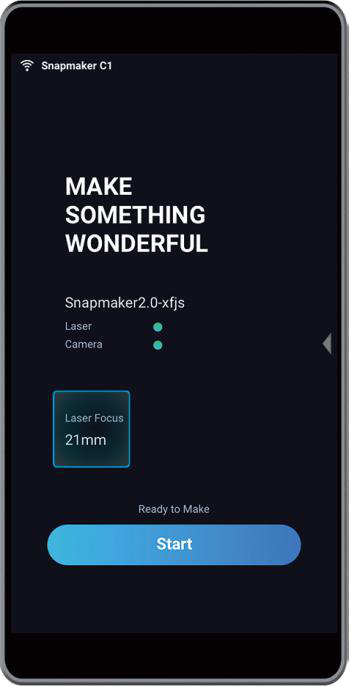
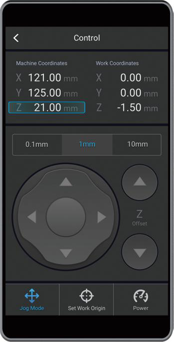
1. Read the current value of the focal length displayed on the touchscreen, we will use ‘21mm’ as an example.
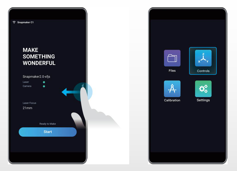
2. Swipe left and select Controls.
3. Use a blank piece of paper, and use X- / X+ / Y- / Y+ / Z- / Z+ to move the laser module to the top of the paper. The machine coordinate of the Z Axis should match the value of the focal length, and both should be ‘21mm’.
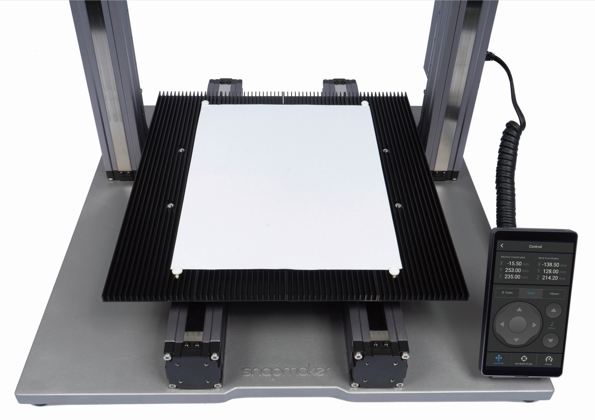
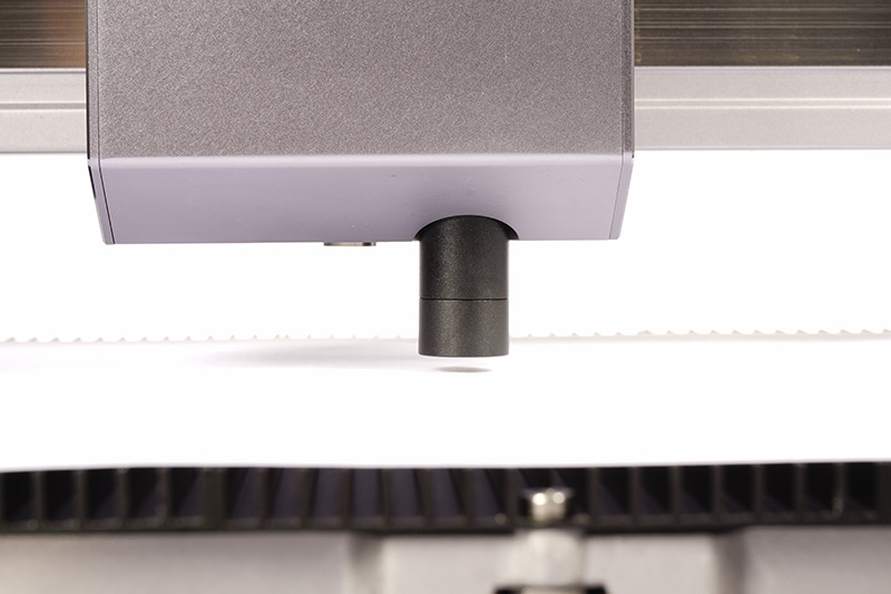
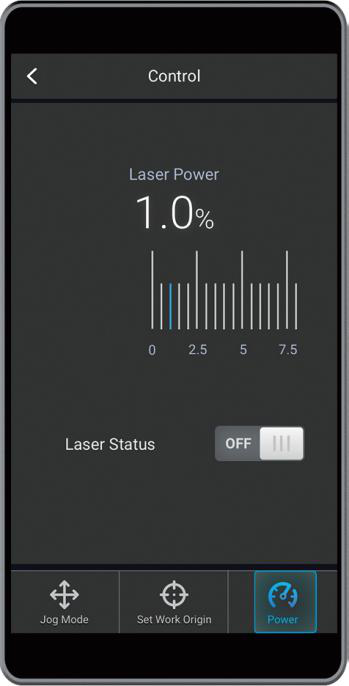
4. Turn the lens hood until it is 1mm away from the paper. If you want to check the light-blocking effect, please do so after you wear your Laser Safety Goggles and select Power. Set a relatively low value (e.g. 1%) for Laser Power and turn on the laser beam.
6.6 Camera Light
When calibrating the camera or using Autofocus to measure the focal length, you can turn on Camera Light for illumination purposes. It helps with taking photos in areas with low light. Camera Light is enabled by default. You can disable it by going to Settings in the main menu, tap Laser, and turn off Camera Light under Laser Settings.
6.7 Camera Calibration
If you have taken off the laser module and tried to reinstall it, or tried to reassemble the machine, recalibrate the camera before you start engraving / cutting using the Camera Capture feature.
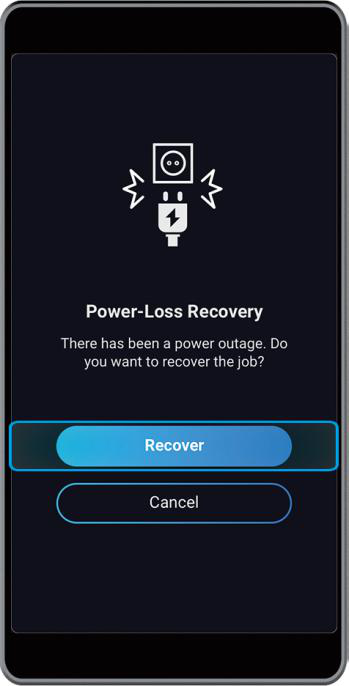
6.8 Resume Print after Power Loss
You do not need to worry about power loss during the engraving / cutting process if you started the process on the touchscreen. You can recover your job after a power loss by tapping Recover on the touchscreen.