3.1 Calibrate the Toolhead Focus
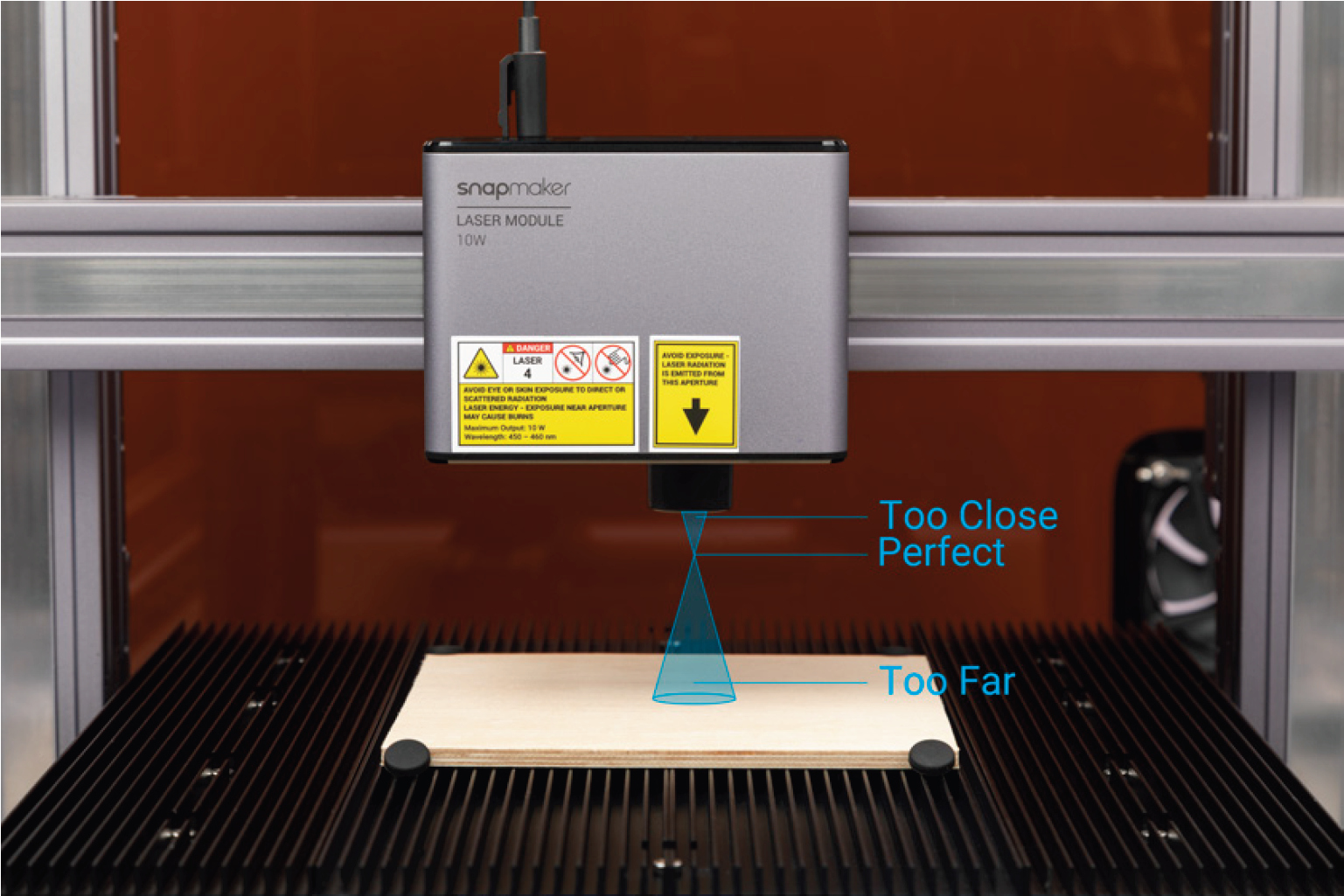
How It Works: Focal Point
To achieve the best focusing result, let the Focal Point fall right on the surface of the material throughout engraving and cutting.
How It Works: Auto Focus
The focal length is the distance from the center of the lens to the focal point of the lens. For the 10W Laser Module, the focal length (f) is a fixed value. Besides, the distance (h1) from the center of the lens to the bottom of the air concentrator hood is also known to the machine. Based on these two values, the machine can calculate the lifting height (h2) of the toolhead after the toolhead touches the laser engraving and cutting platform, and thus do automatic focusing.

Start the Toolhead Focus Calibration
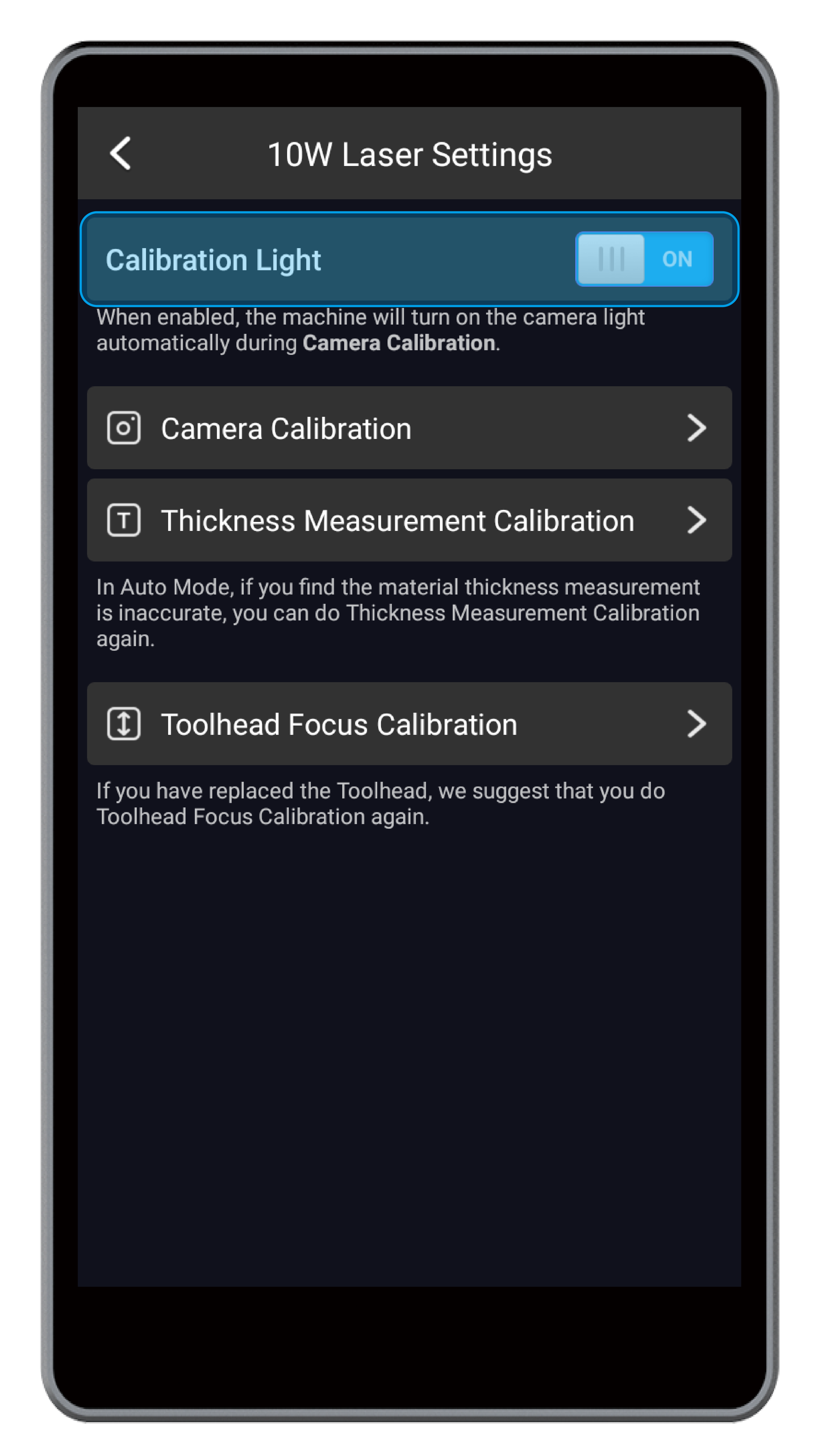
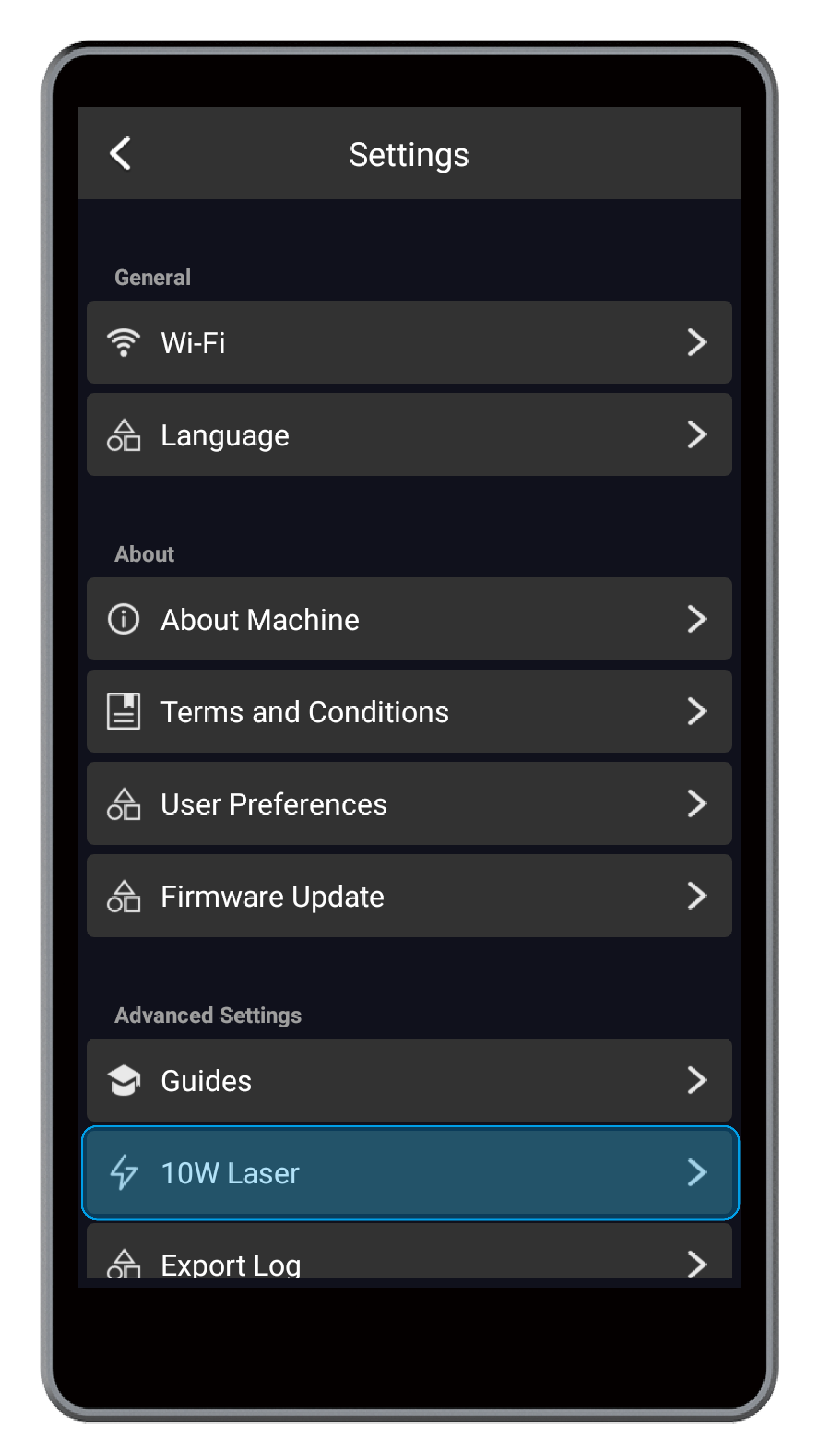
(1) On the Home Screen of the Touchscreen, swipe left to enter the APP List Screen. Tap Settings > 10W Laser > Toolhead Focus Calibration.
(2) Tap Start to launch Toolhead Focus Calibration. The machine will move the 10W Laser Module to the central position above the laser engraving and cutting platform.
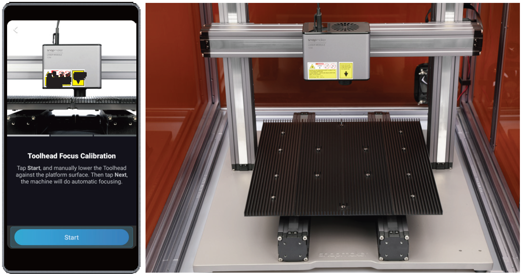
![]() If the toolhead has not been to its home position after you turn on the machine, you need to tap Going Home, and the machine will move the toolhead in X, Y, and Z orientations to the pre-defined position, whose coordinates serve as reference points.
If the toolhead has not been to its home position after you turn on the machine, you need to tap Going Home, and the machine will move the toolhead in X, Y, and Z orientations to the pre-defined position, whose coordinates serve as reference points.
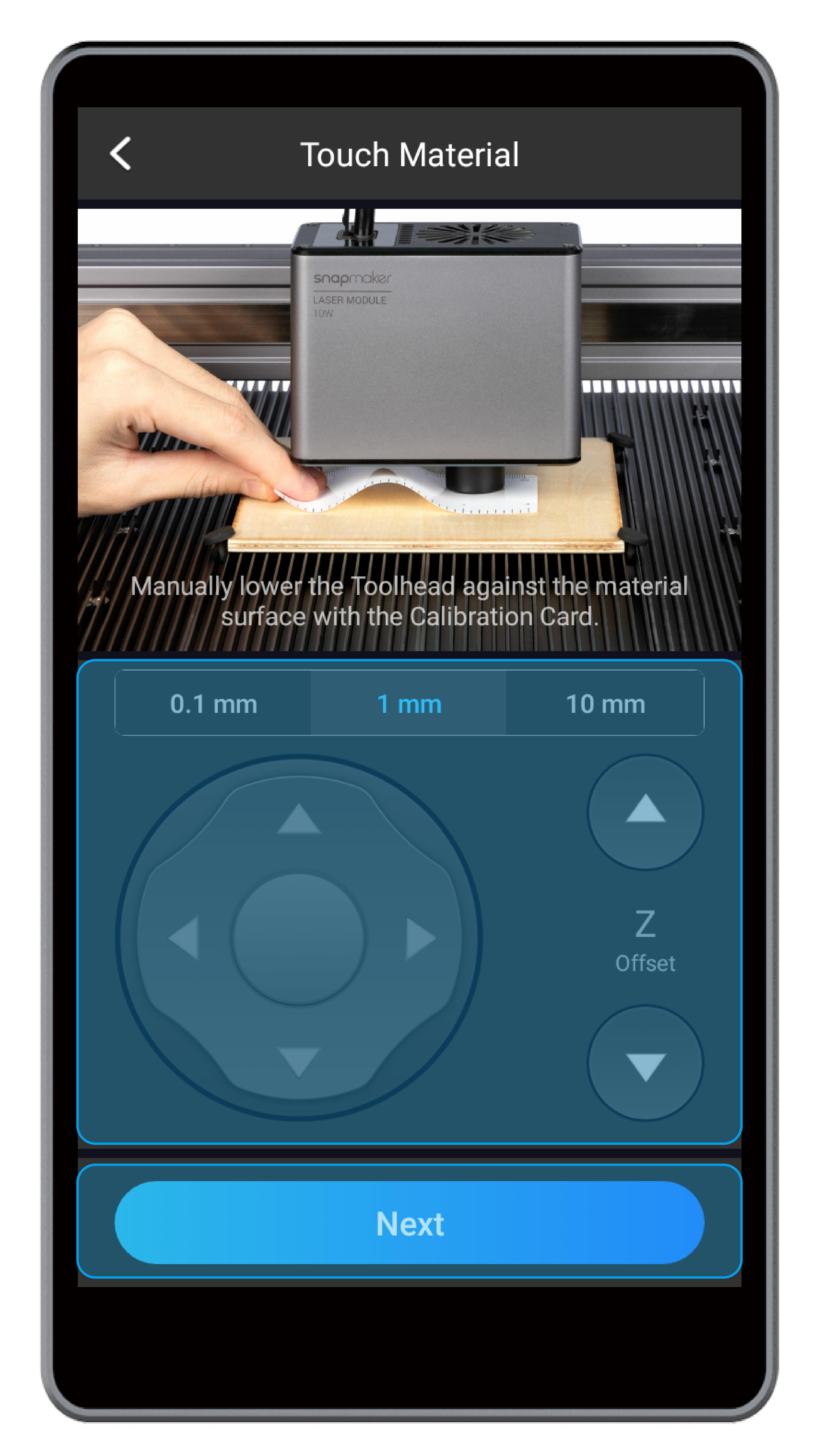
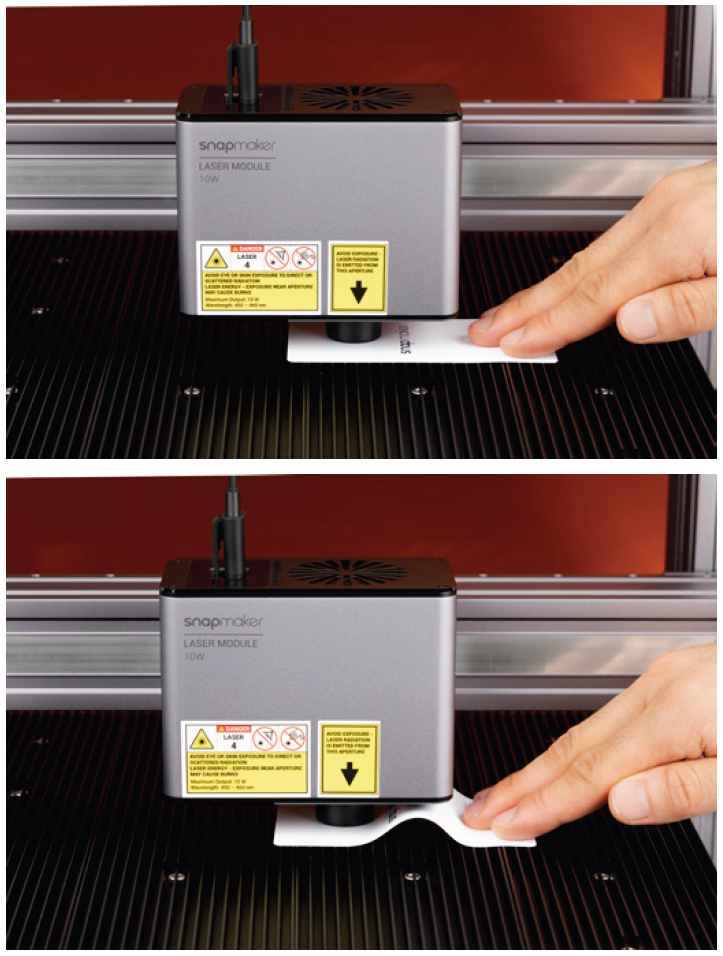
(3) Place the calibration card or a piece of A4 paper between the 10W Laser Module and laser engraving and cutting platform. Keep adjusting the Z Offset until you feel slight resistance when you pull out the calibration card, and it should be wrinkled when you push it forward. After you finish the adjustment, tap Complete.
3.2 Calibrate the Thickness Measurement System
How It Works: Measure Material Thickness
The 10W Laser Module contains a thickness measurement system that uses the triangulation technique to measure the material thickness. Firstly, the red laser emitter projects a red dot on the material surface. Then, the camera captures an image of the red dot. Finally, the thickness measurement system analyzes the image data to calculate the material thickness.
Before you use the thickness measurement system for the first time, you need to calibrate its initial parameters.

![]() The red laser emitter is a Class 2 laser product. Do not look directly into its aperture when laser beam is emitted.
The red laser emitter is a Class 2 laser product. Do not look directly into its aperture when laser beam is emitted.
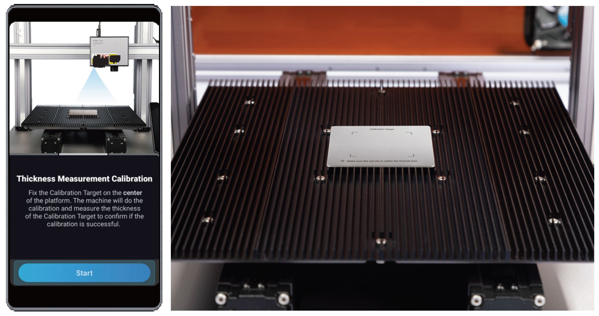
Start the Thickness Measurement Calibration
(1) On the Home Screen of the Touchscreen, swipe left to enter the APP List Screen. Tap Settings > 10W Laser > Thickness Measurement Calibration.
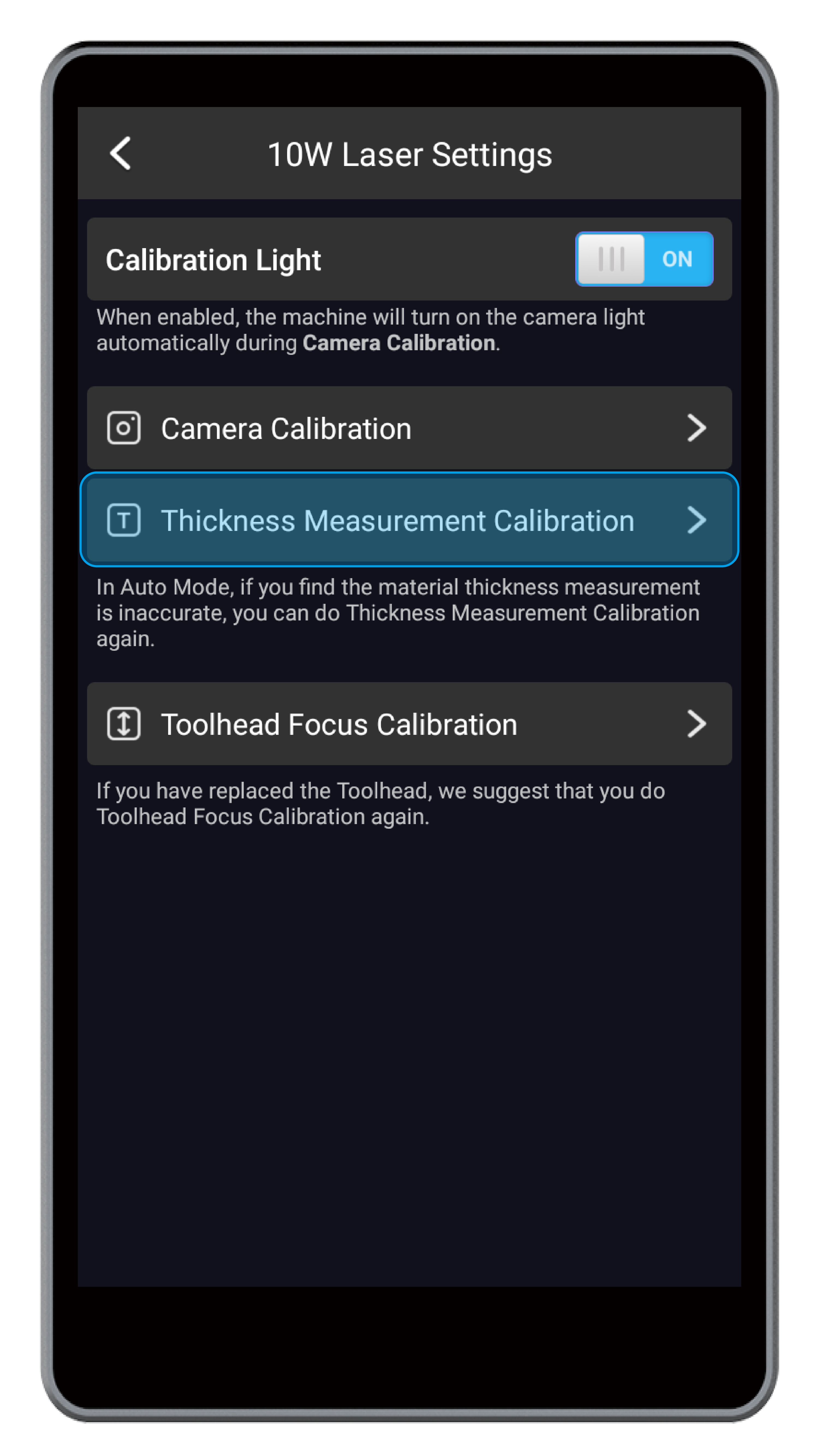
(2) Place the provided calibration target on the center of the laser engraving and cutting platform, and tap Start.
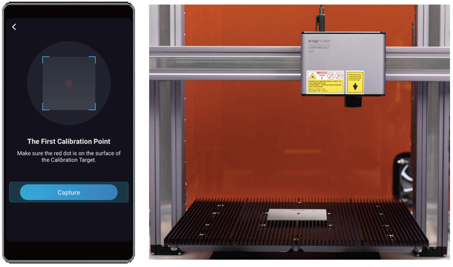
(3) Ensure that the red dot falls within the framed area of the calibration target, and click Capture. The machine will automatically capture the first and second calibration points to complete the calibration and measure the thickness of the calibration target to verify the result.
![]() If you have detached the 10W Laser Module from the X Axis or reassembled the machine, you need to recalibrate the thickness measurement system.
If you have detached the 10W Laser Module from the X Axis or reassembled the machine, you need to recalibrate the thickness measurement system.
3.3 Calibrate the Camera
How It Works: Camera Capture
The 10W Laser Module contains a wide-angle HD camera to capture the image of the work area, generating a background to edit the laser engraving and cutting objects. By using Camera Capture, you can position the laser engraving and cutting area.
Start the Camera Calibration
(1) On the Home Screen of the Touchscreen, swipe left to enter the APP List Screen. Tap Settings > 10W Laser > Camera Calibration.
(2) Remove the calibration target. Fasten a piece of blank A4 paper on the center of the laser engraving and cutting platform, and tap Start.
(3) Put on the laser safety goggles, and tap Start. The machine will cut a square on the paper and use the square to calibrate the camera.
![]() If you have detached the 10W Laser Module from the X Axis or reassembled the machine, you need to recalibrate the camera.
If you have detached the 10W Laser Module from the X Axis or reassembled the machine, you need to recalibrate the camera.
3.4 Prepare the Material
Select the Material
To protect your safety as well as the environment, select the materials to be engraved and cut based on the following rules:
- Do not use inflammable and explosive materials;
- Do not use highly reflective materials;
- Ensure that the material will not produce hazardous and toxic fumes when being laser engraved or cut, or the produced fumes can be purified by your air purifier.
In addition, to ensure a high-quality engraving and cutting effect, the material needs to meet certain requirements in shape and size.
- Lists of Supported Materials
You can select materials from the supported lists provided by Snapmaker. Snapmaker screens and tests these materials to ensure that they are safe and can be engraved and cut by the 10W Laser Module.
If the material you use is not on the corresponding list, ensure that you know enough information about the material properties and take precautions against potential hazards that occur during laser engraving and cutting.
|
Supported Materials for Engraving |
Basswood, Pinewood, Plywood, Beech, Walnut, Bamboo, MDF, Painted Metal, Copper Clad Laminate, Tinplate, Stainless Steel, Anodized Aluminum, Dark Glass, Slate, Brick, Ceramic, Jade, Marble, Shale, Leather, Fabric, Canvas, Corrugated Paper, Cardboard, Plastic, Dark Acrylic (Blue excluded), etc. |
|
Supported Materials for Cutting |
Basswood, Pinewood, Plywood, Beech, Walnut, Bamboo, MDF, Leather, Fabric, Canvas, Corrugated Paper, Cardboard, Plastic, Dark Acrylic (Blue excluded), etc. |
- Shape
The 10W Laser Module engraves and cuts materials with a fixed focal length. To ensure a consistent effect, you should use a material that has a flat surface to be engraved and cut.
- Size
The material size should not exceed the work area of the 10W Laser Module. The work area varies with machine models.
|
Machine Models |
Work Area |
|
A350/A350T/F350 |
320 mm × 350 mm |
|
A250/A250T/F250 |
230 mm × 250 mm |
Measure the Material Thickness
- Automatically Measure the Material Thickness
The 10W Laser Module contains a thickness measurement system that automatically measures material thickness. To avoid thickness measurement failure, ensure that the material meet the following requirements:
-
- The material thickness is less than or equal to 50 mm;
- The material texture is not transparent.
- The material surface is not glossy or specular.
- The material color is not red or black.
- Manually Measure the Material Thickness
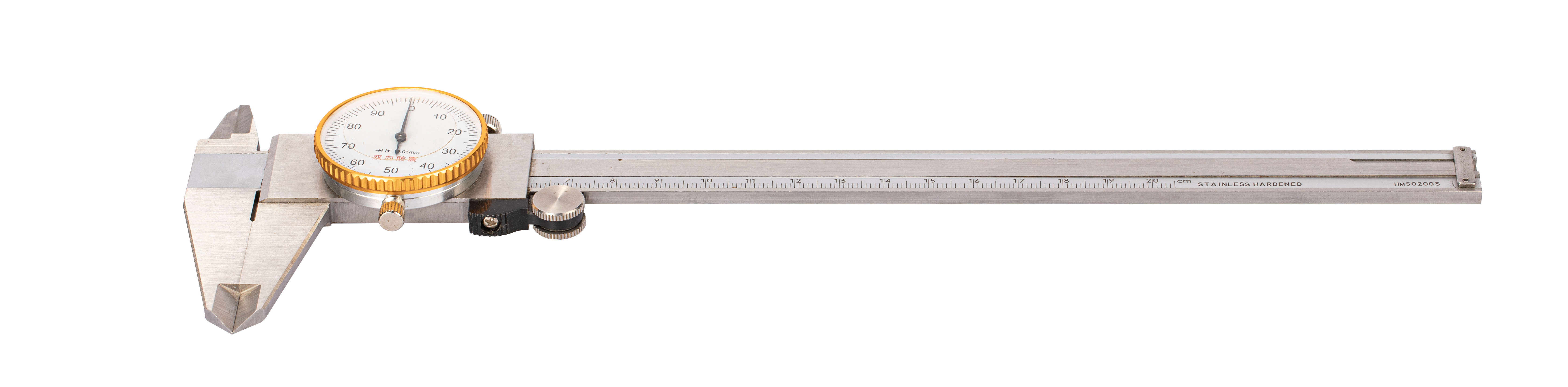
If the material does not meet the requirements of automatic measurement, you can manually measure the material thickness with a vernier caliper.
![]() Manually measuring material thickness is not a must-do step. Only when you start laser engraving and cutting on Luban and select the manual mode, do you need to manually measure the material thickness.
Manually measuring material thickness is not a must-do step. Only when you start laser engraving and cutting on Luban and select the manual mode, do you need to manually measure the material thickness.
Fasten the Material
- Purposes
Fastening the material is to prevent position changes and curling during laser engraving and cutting. This step is important for producing a high-quality engraving and cutting result.
- Methods
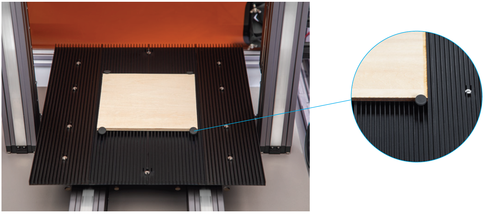
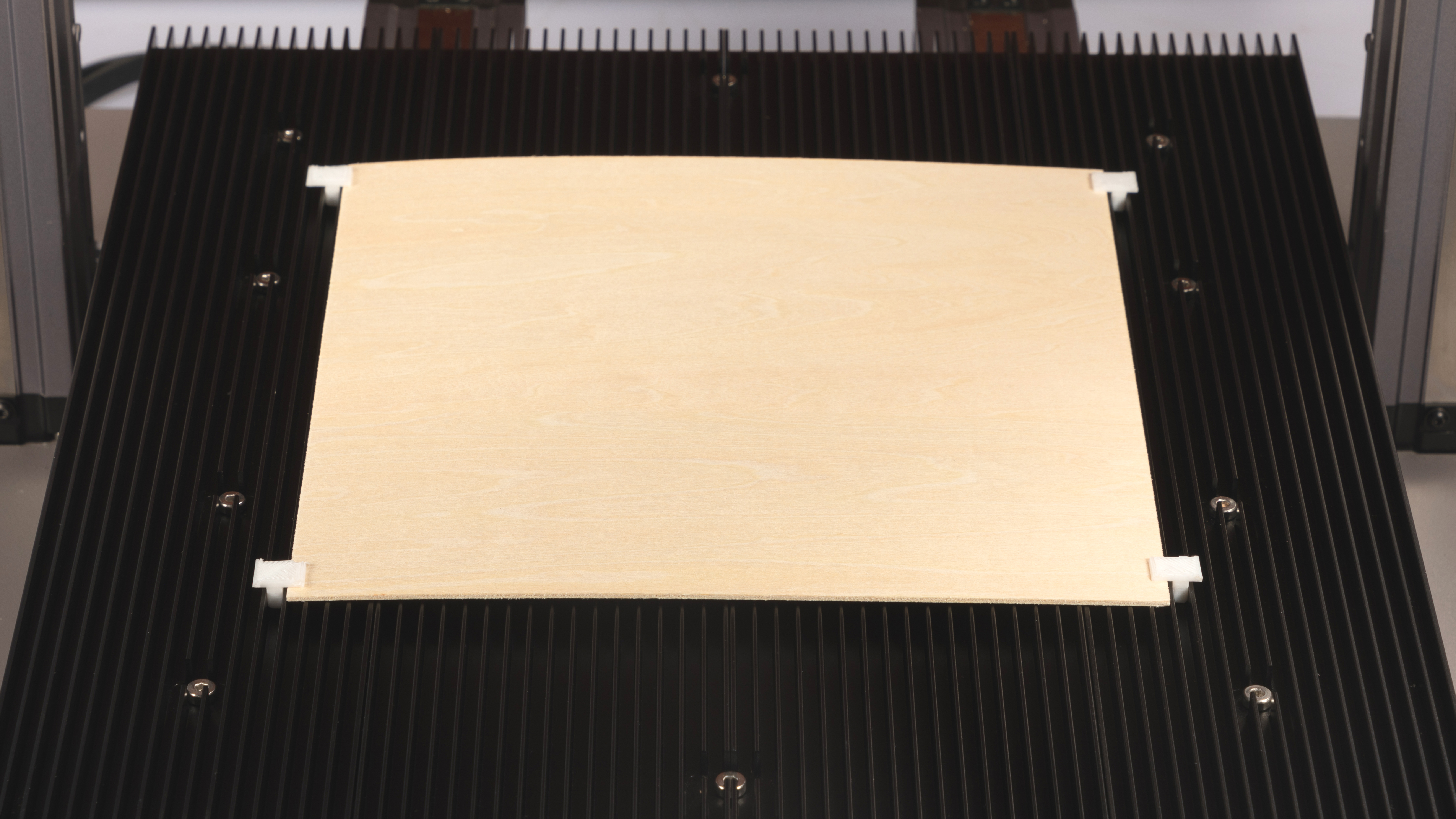
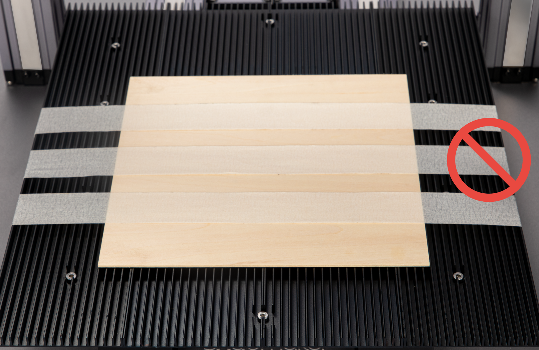
You can use the provided silicon plugs to fasten the material. As illustrated in the following picture, place the material on the laser engraving and cutting platform, and fasten it with at least four silicone plugs.
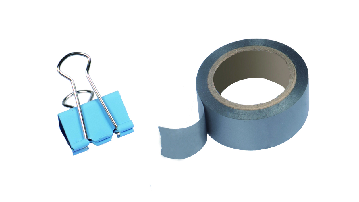
You can also use office products such as tapes and binder clips.
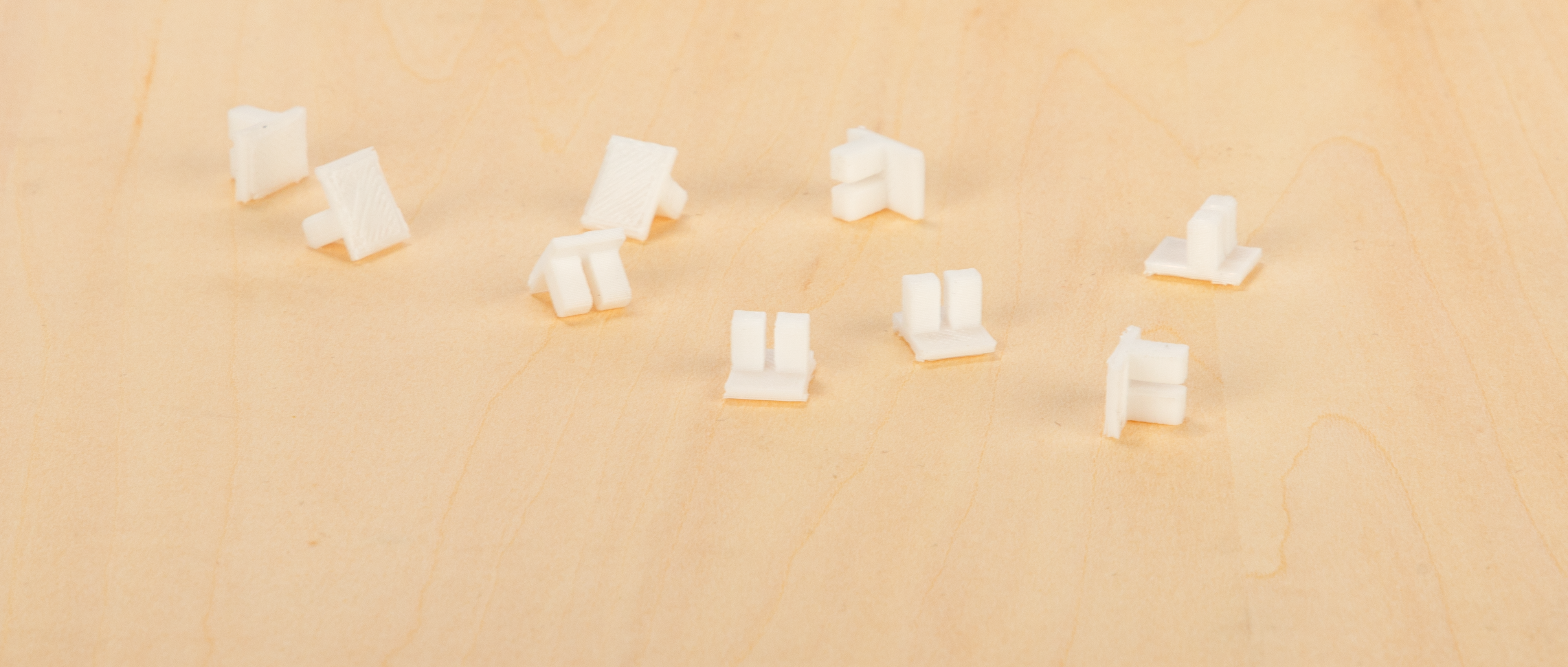
You can even use the 3D printer to make DIY fasteners. The following picture shows a 3D printed widget specially designed to secure laser engraving and cutting materials.
- Cautions
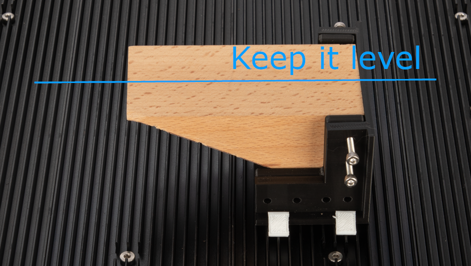
Ensure that the surface to engrave or cut remains level.
Ensure that the fastening tools will not collide with any portions of the machine.
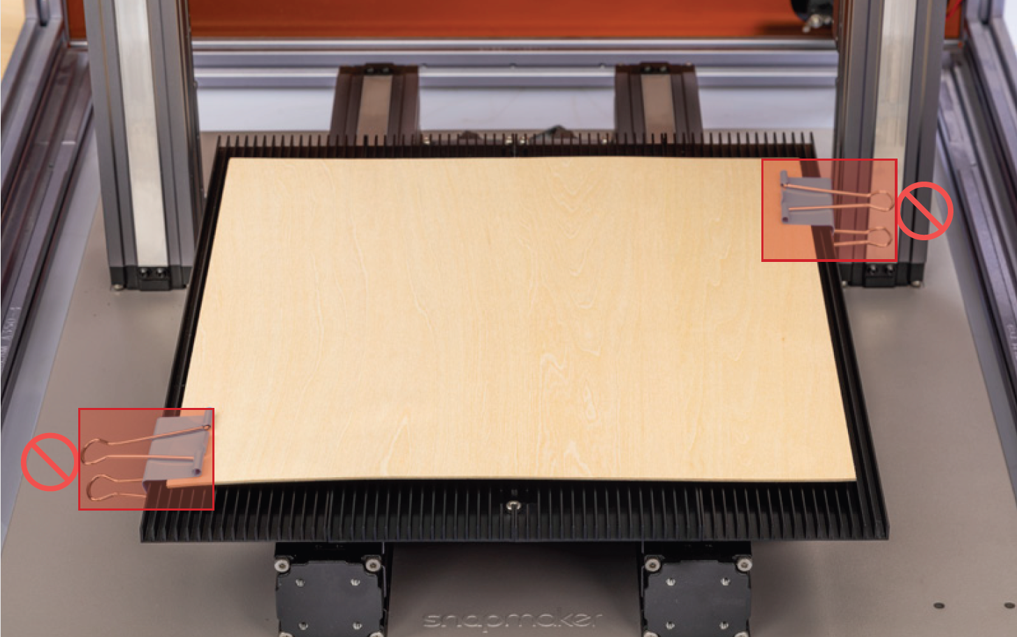
Ensure that the fastening tools remain out of the engraving and cutting paths.
3.5 Connect the Machine to Luban
Connect Via Wi-Fi
(1) Connect your computer and machine to the same Wi-Fi network.
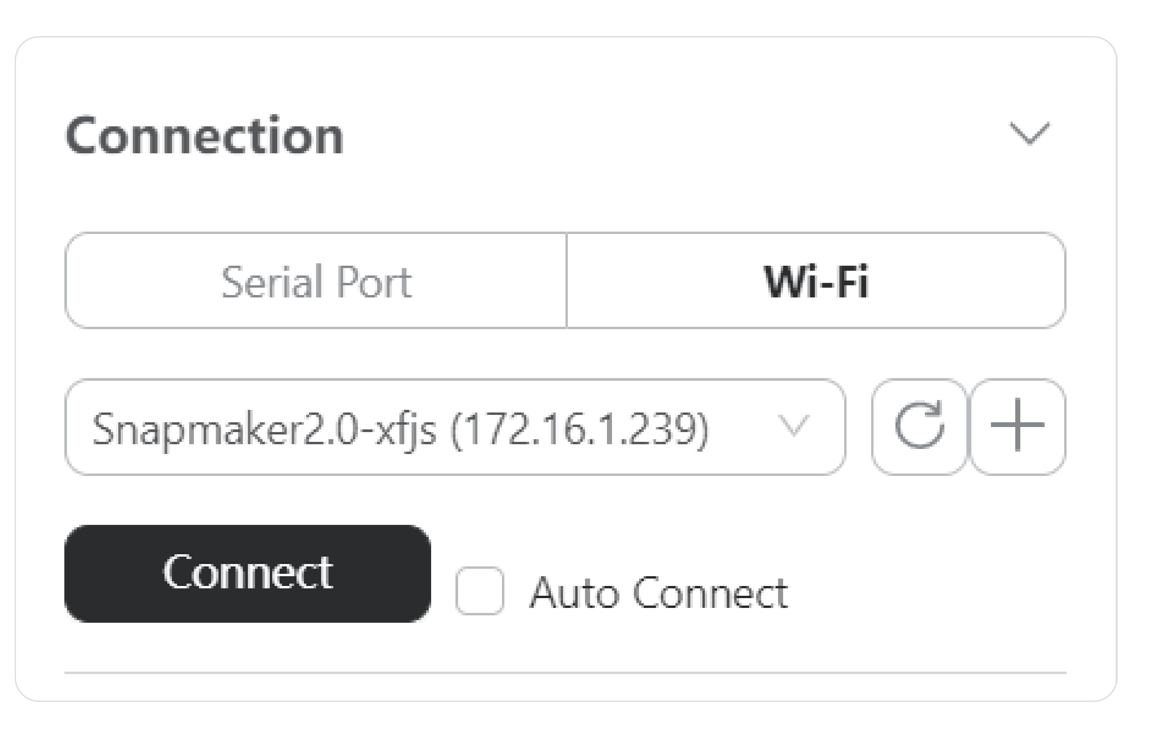
(2) On your computer, open Luban. On the Home page of Luban, click Workspace ![]() . On the Connection panel of the Workspace, select Wi-Fi > click Refresh
. On the Connection panel of the Workspace, select Wi-Fi > click Refresh  > select your machine from the drop-down list > click Connect.
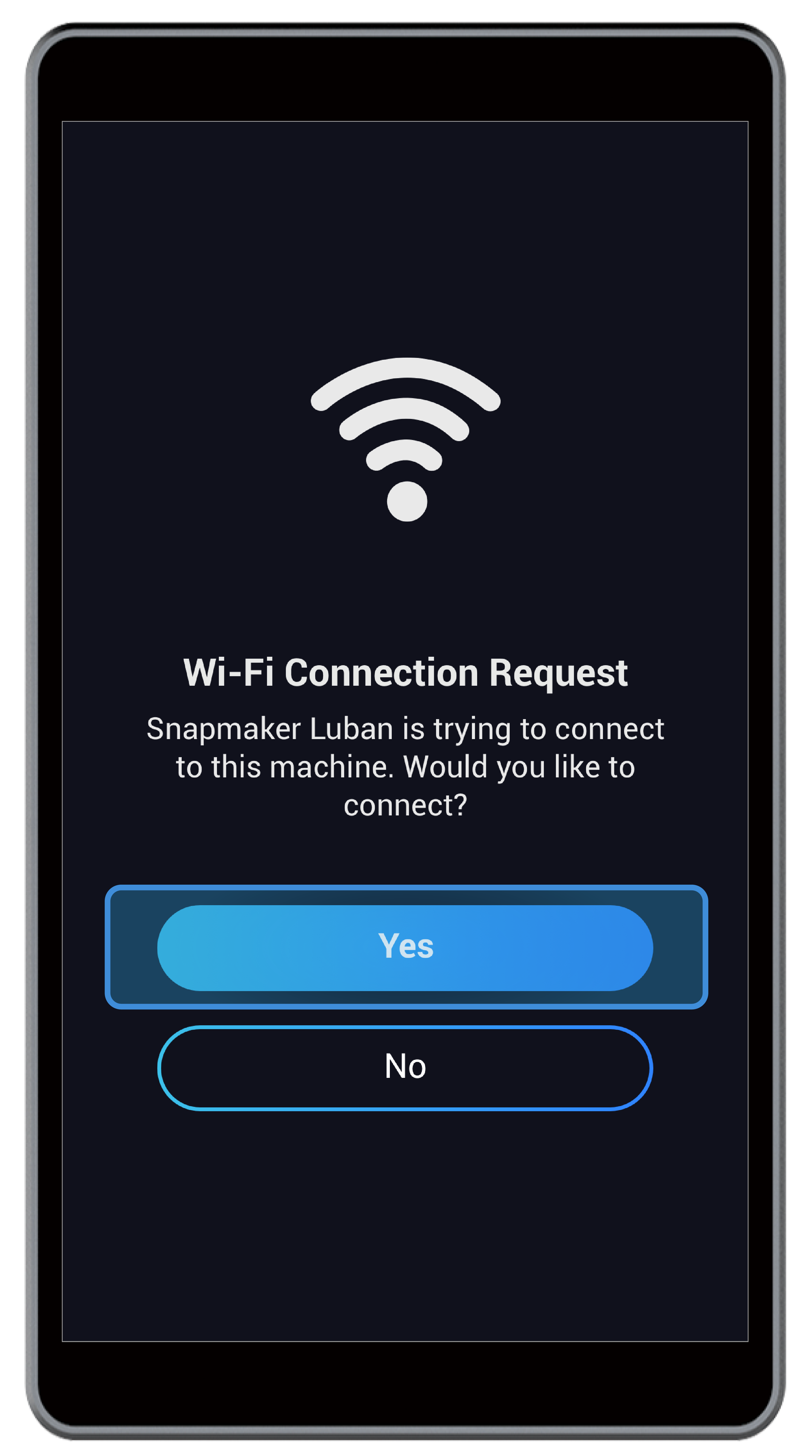
(3) On the Touchscreen, tap Yes to confirm the connection.
![]() When the machine is connected to Luban via Wi-Fi, you cannot operate it on the Touchscreen.
When the machine is connected to Luban via Wi-Fi, you cannot operate it on the Touchscreen.
![]() If the machine is disconnected from Luban, ongoing engraving and cutting jobs will not stop on the machine. You must tap Confirm on the Touchscreen.
If the machine is disconnected from Luban, ongoing engraving and cutting jobs will not stop on the machine. You must tap Confirm on the Touchscreen.
![]() If the machine is disconnected from Luban when the Laser Power is turned on, the 10W laser emitter will not automatically turn off. You must go to Control > Laser Power > Laser Status to manually turn it off.
If the machine is disconnected from Luban when the Laser Power is turned on, the 10W laser emitter will not automatically turn off. You must go to Control > Laser Power > Laser Status to manually turn it off.
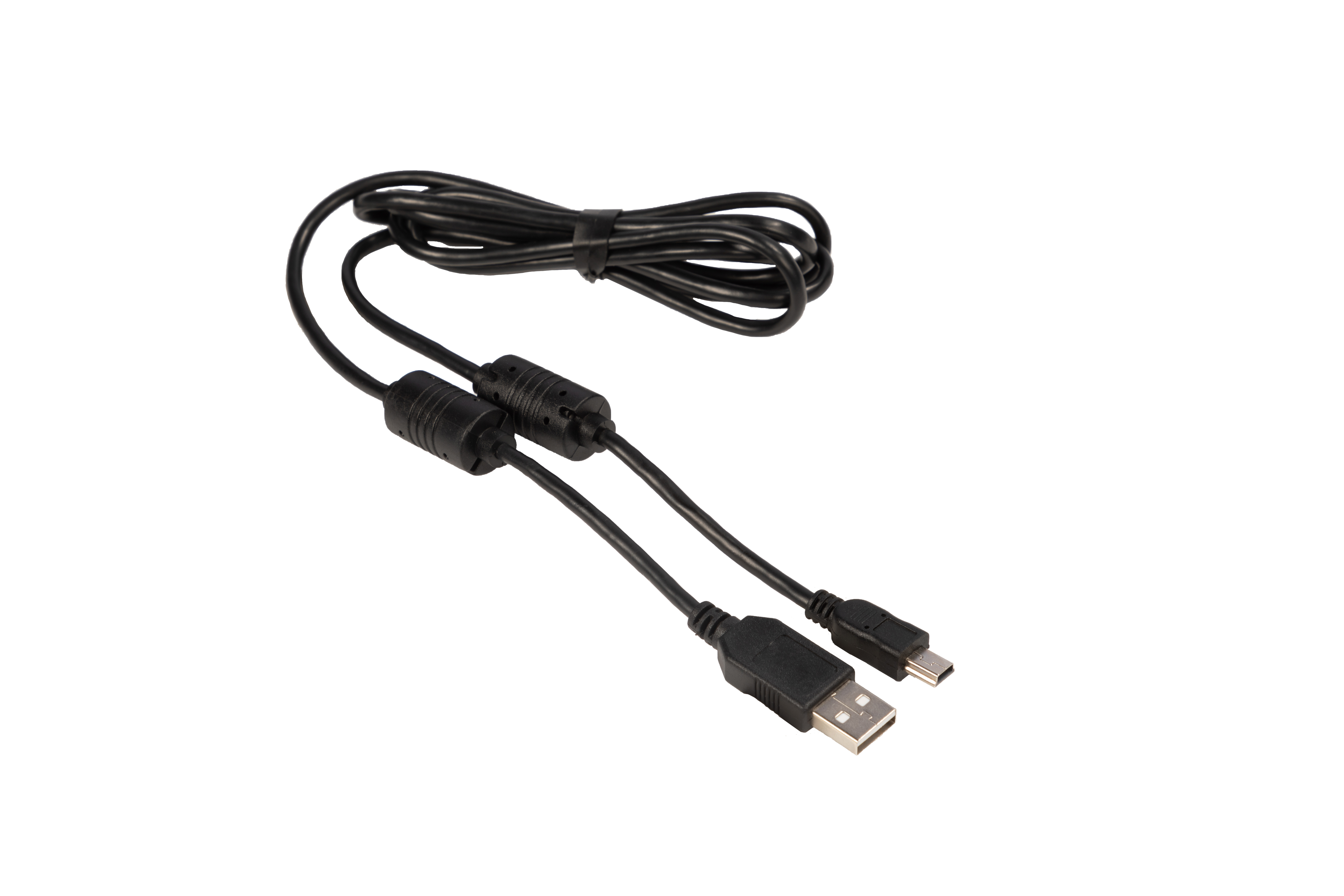
Connect via USB Cable
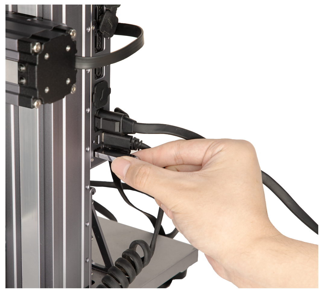
(1) As illustrated in the following picture, insert the Type-A plug of the provided USB cable into the computer, and the other end into the Controller of the machine.
(2) On your computer, open Luban. On the Home page of Luban, click Workspace ![]() .
.
(3) On the Connection panel of the Workspace, select Serial Port > click Refresh > select your machine from the drop-down list > click Connect.
![]() If you cannot find the port, unplug the USB cable and try again. You may need to download and install the driver from https://snapmaker.com/product/snapmaker-2/downloads.
If you cannot find the port, unplug the USB cable and try again. You may need to download and install the driver from https://snapmaker.com/product/snapmaker-2/downloads.
![]() When the machine is connected with Luban via USB cable, you can control the movement of the toolhead, turn on or off the laser, and start laser engraving and cutting on Luban. However, you cannot use the Camera Capture feature or the Auto Mode to start laser jobs. Besides, if the USB cable is disconnected, the ongoing laser job will stop.
When the machine is connected with Luban via USB cable, you can control the movement of the toolhead, turn on or off the laser, and start laser engraving and cutting on Luban. However, you cannot use the Camera Capture feature or the Auto Mode to start laser jobs. Besides, if the USB cable is disconnected, the ongoing laser job will stop.
![]() If the machine is disconnected from Luban when the Laser Power is turned on, the 10W laser emitter will not automatically turn off. You must go to Control > Laser Power > Laser Status to manually turn it off.
If the machine is disconnected from Luban when the Laser Power is turned on, the 10W laser emitter will not automatically turn off. You must go to Control > Laser Power > Laser Status to manually turn it off.
3.6 Prepare the G-code File
How It Works: G-code Files
G-code is a computer numerical control (CNC) programming language. A G-code file contains a series of instructions written in G-code. After you select a laser engraving and cutting object, you must first convert it to a G-code file. Then, send the G-code file to the machine, so that the machine can work following the G-code instructions.
Generate the G-code File
(1) On your computer, open Luban. On the menu bar, select Settings > Machine Settings to open the Preferences pop-up window. Select the machine model and the type of the Laser Module, and click Save.
(2) Connect your machine with Luban (see 3.5 Connect the Machine to Luban).
 /
/ 
![]() If you transfer the G-code file to the machine by using the USB flash drive, and start laser engraving and cutting on the Touchscreen, skip step (2).
If you transfer the G-code file to the machine by using the USB flash drive, and start laser engraving and cutting on the Touchscreen, skip step (2).
![]() If you connect your machine to Luban via USB cable, you cannot use the Camera Capture feature nor the Auto Mode to start laser engraving and cutting on Luban.
If you connect your machine to Luban via USB cable, you cannot use the Camera Capture feature nor the Auto Mode to start laser engraving and cutting on Luban.
(3) On the top-left corner of Luban, click Back to go back to the Home Select Laser > 3-axis to enter the Laser G-code Generator ![]() .
.
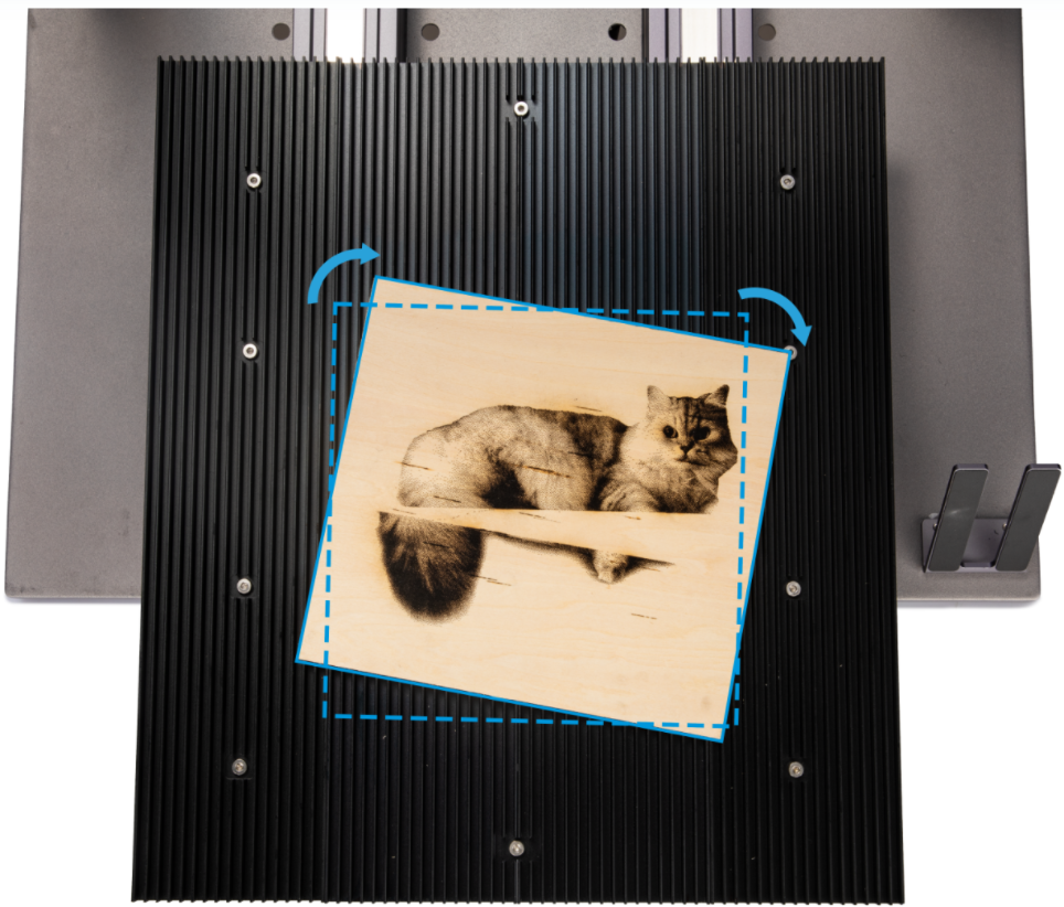
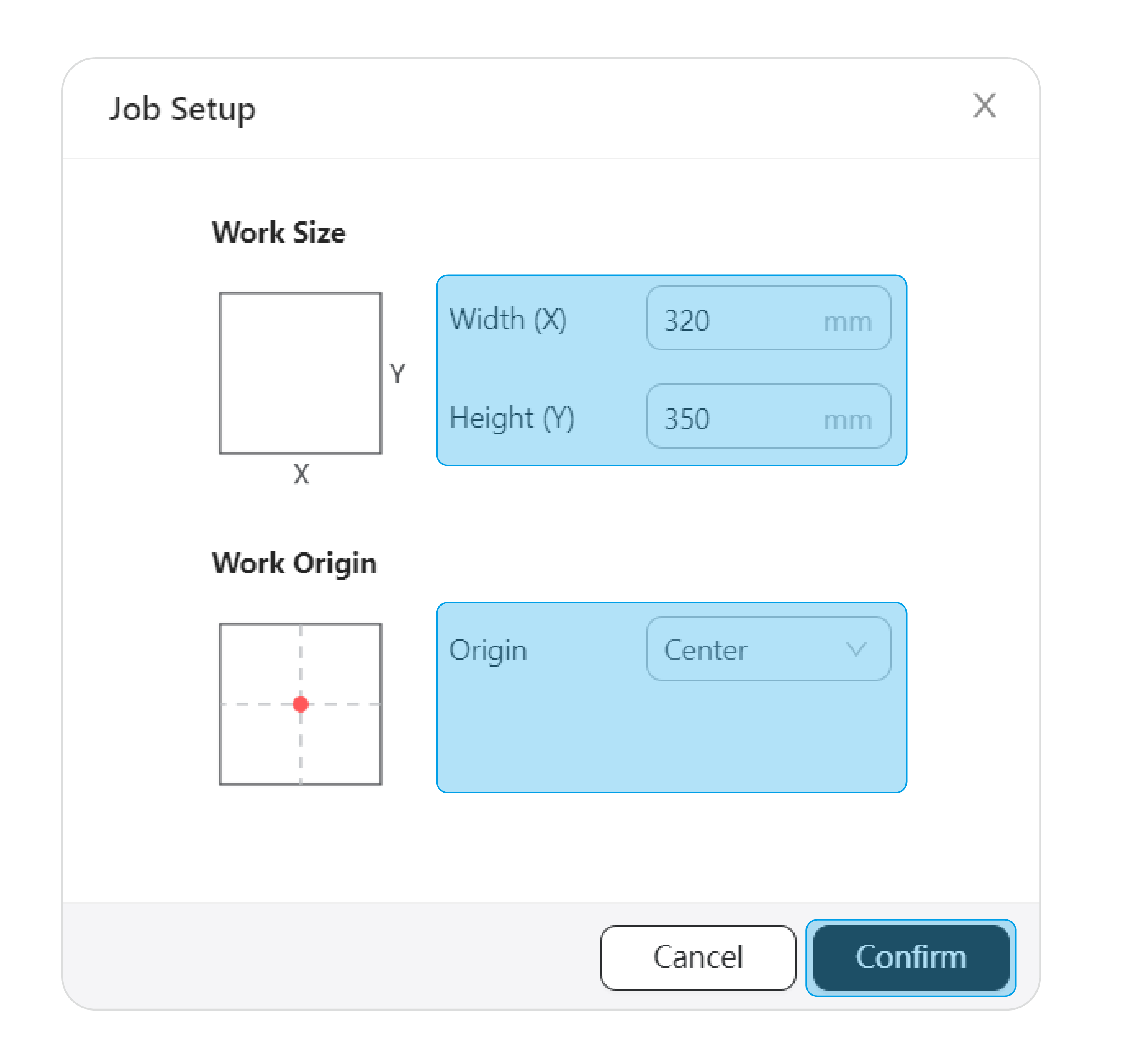
(4) On the Job Setup pop-up window, set Work Size based on your material size and set Work Origin to determine the relative position of the work origin on the material. After you finish setting, click Confirm.
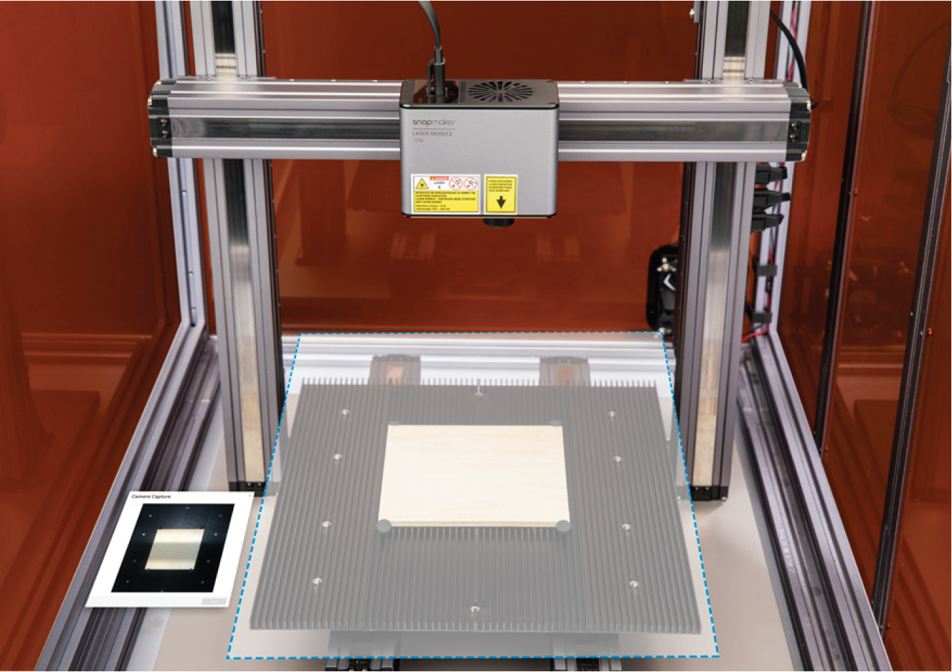
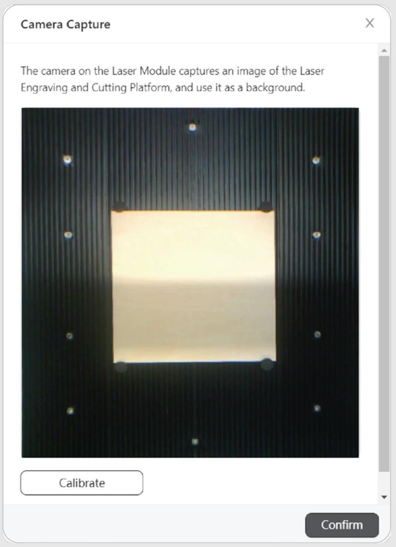
(5) On the menu bar of Luban, select Camera Capture > Add Background, and click Start. The machine will take a photo of the work area and use it as the background for the engraving or cutting object. After the photo is captured, click Confirm.

![]() Skip this step if you use work origin to determine the position of your engraving and cutting object.
Skip this step if you use work origin to determine the position of your engraving and cutting object.
![]() If the captured image is twisted out of shape, click Calibrate to manually calibrate the camera.
If the captured image is twisted out of shape, click Calibrate to manually calibrate the camera.
(a) Zoom into the image and move the lines until they perfectly match the square, and then click Confirm > Apply to see the finished image. If the object in the photo remains twisted, click Calibrate and repeat this step.
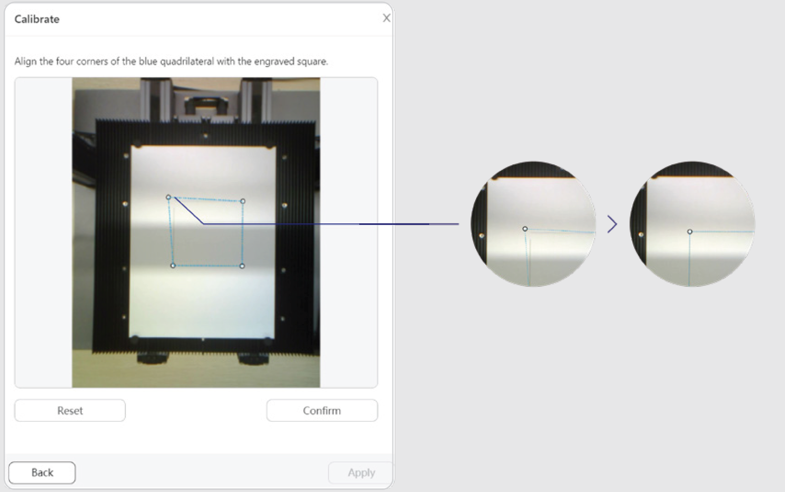
(b) After you obtain a normal-shaped image, click Confirm. The finished image will be loaded in the coordinate system.
(6) On the left toolbar, click  to select an object file from your computer and add it to the canvas.
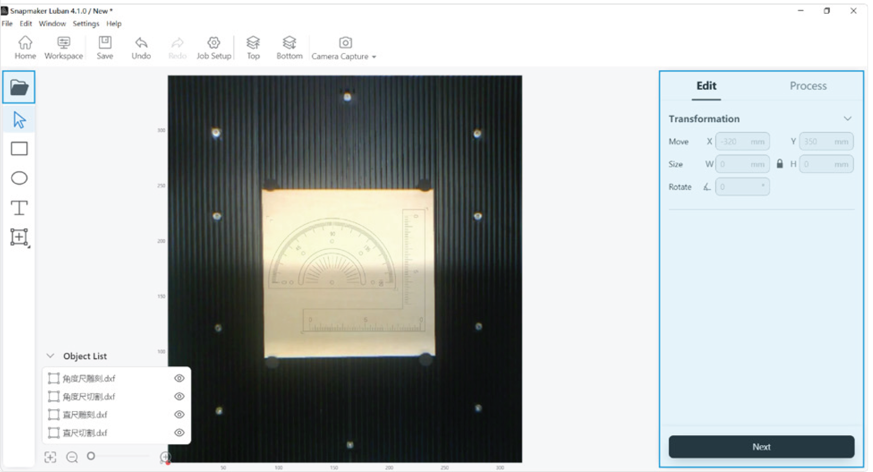
![]() Currently, the Laser G-code Generator of Snapmaker Luban supports to process the following file formats: .svg, .png, .jpeg, .jpg, .bmp, .dxf, and .stl. If you add a .stl file, you can set the model size and material thickness. Then, Snapmaker Luban automatically transforms the .stl object into multiple layers of vector images.
Currently, the Laser G-code Generator of Snapmaker Luban supports to process the following file formats: .svg, .png, .jpeg, .jpg, .bmp, .dxf, and .stl. If you add a .stl file, you can set the model size and material thickness. Then, Snapmaker Luban automatically transforms the .stl object into multiple layers of vector images.
(7) On the object list, click to select the object. On the Edit panel to the right of the canvas, you can set the position, size, rotation angle, and processing mode for the object. After you finish editing, click Next to enter the Process panel.
(8) On the object list, click to select the object. On the Process panel to the right of the canvas, click Create Toolpath.
- You can select the material you use and its processing method in the Preset Based on the selected Preset option, Luban will generate a set of recommended parameters.
- You can also configure work parameters on yourself.
After you finish toolpath settings, click Save > Generate G-code and Preview.

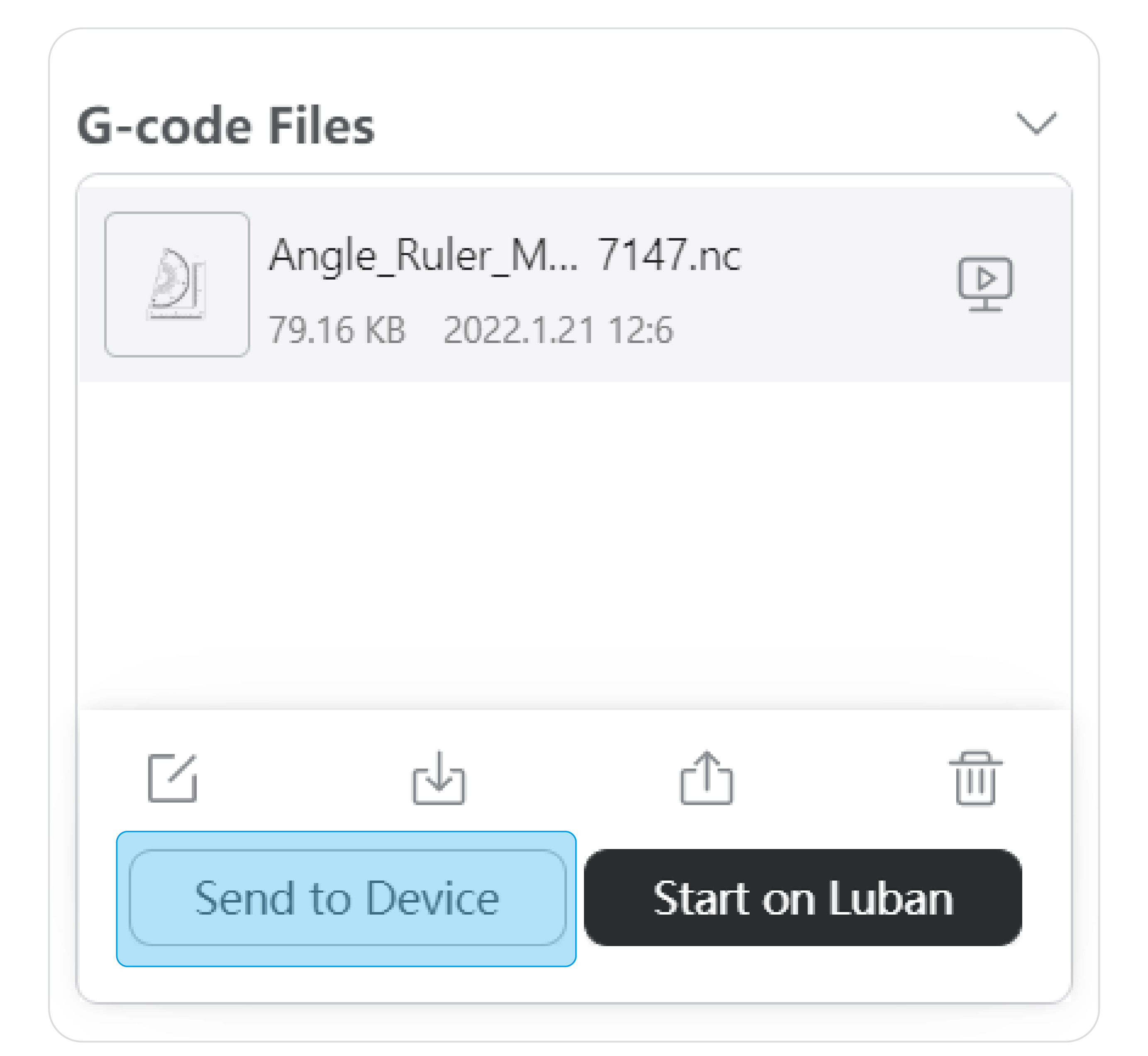
(9) Click Export. Select Load G-code to Workspace or Export G-code to File.
- If you select Load G-code to Workspace, and the machine is connected with Luban, you can send the G-code file to the machine from Luban (only when using Wi-Fi connection) or start laser engraving and cutting on Luban.
- If you select Export G-code to File, you can save the G-code file to your local computer.
3.7 Transfer the G-code File
Transfer via Wi-Fi
(1) Connect the machine to Luban via Wi-Fi (see 3.5 Connect the Machine to Luban: Connect via Wi-Fi).
(2) After you generate the G-code file on Luban, select Export > Load G-code to Workspace. On the G-code Files panel, select the G-code file to be transferred and click Send to Device.
(3) On the Touchscreen, tap Got It to receive the G-code file.
(4) To find the G-code file, swipe left on the Home Screen of the Touchscreen > tap Files > select Local.
Transfer via USB Flash Drive
(1) After you generate the G-code file on Luban, select Export > Export G-code to File. Save the exported file (in .nc format) to your USB flash drive.
(2) Insert the USB flash drive into the Controller of the machine.
(3) To find the G-code file, swipe left on the Home Screen of the Touchscreen > tap Files > select USB.
3.8 Start Engraving and Cutting
How It Works: Work Origin
The work origin corresponds to the (0, 0) coordinate origin on Luban. By setting the work origin and running boundary, you can find out where the engraving and cutting will take place.
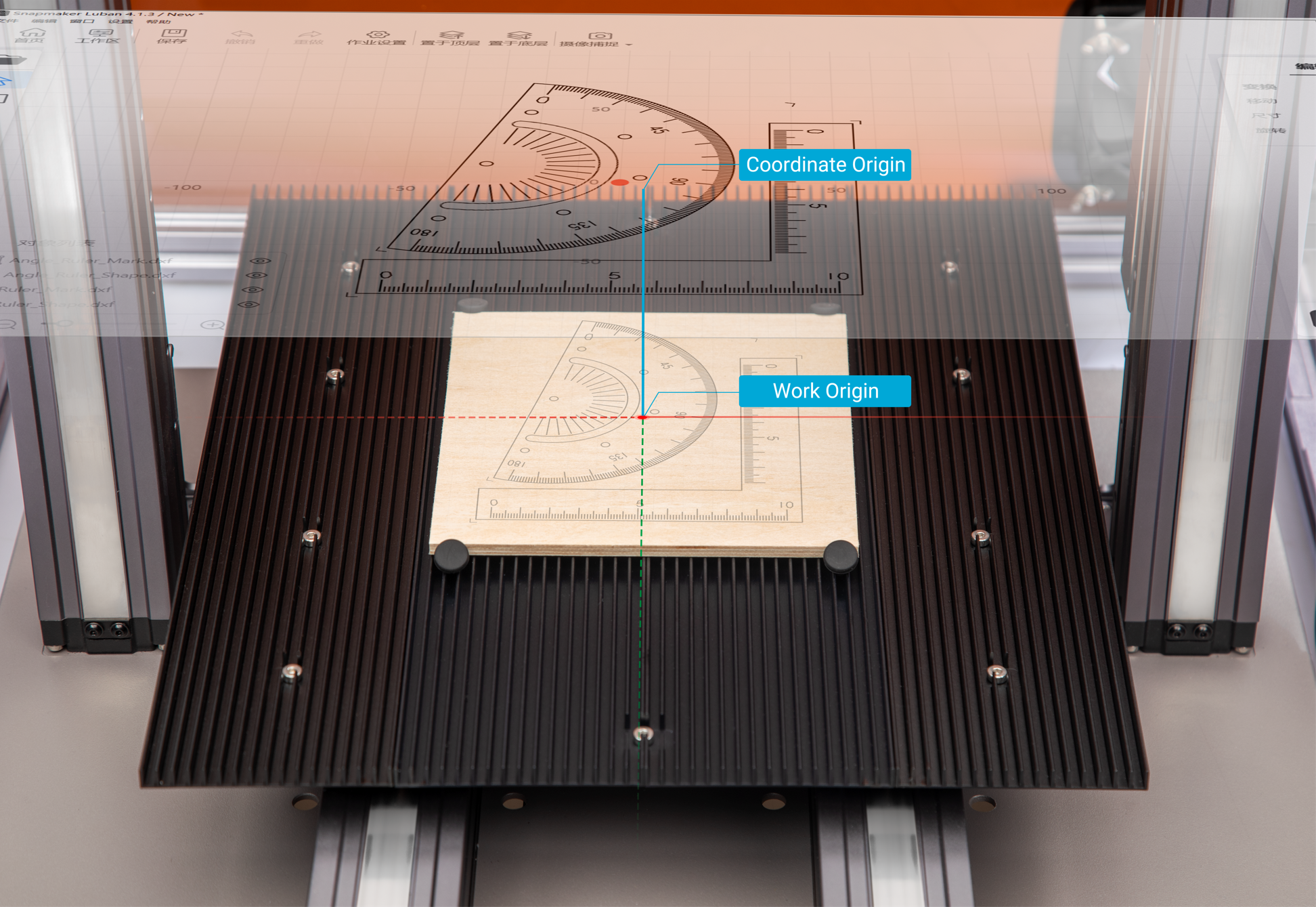
![]() If you use the Camera Capture feature to determine the engraving and cutting position, you do not need to set the work origin.
If you use the Camera Capture feature to determine the engraving and cutting position, you do not need to set the work origin.
Start Engraving and Cutting on the Touchscreen
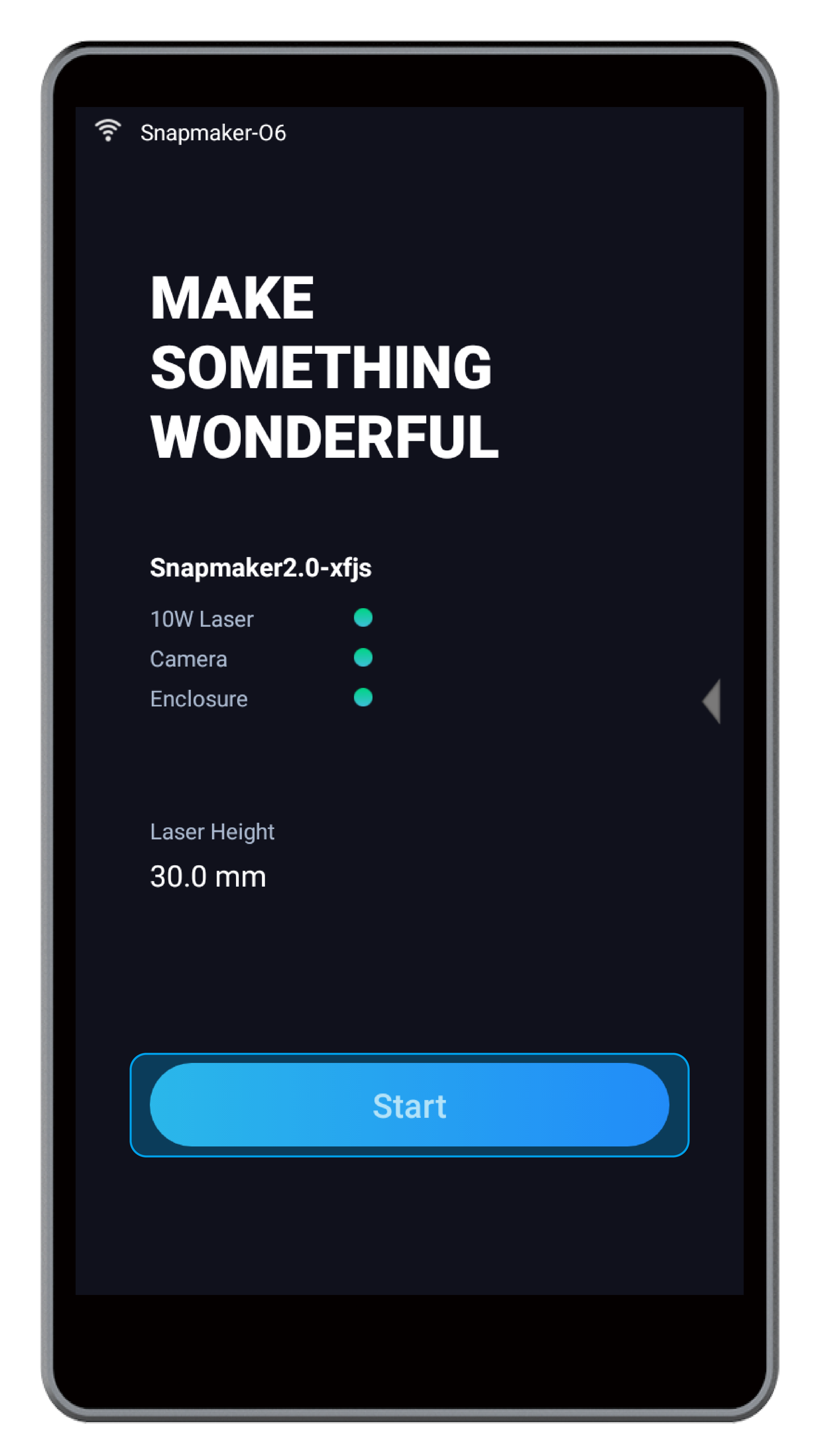
(1) On the Home Screen of the Touchscreen, tap Start.
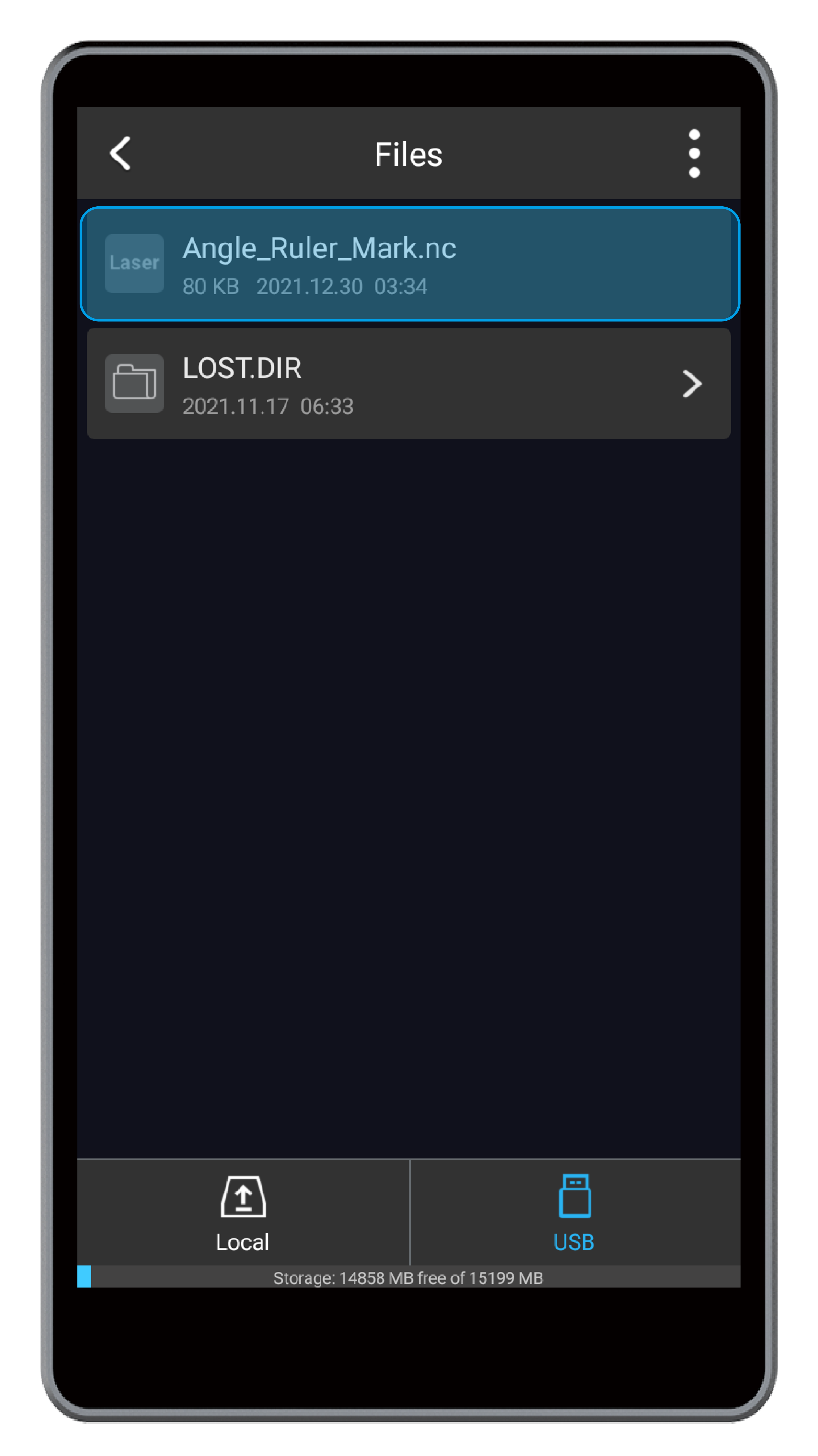
(2) Choose the G-code file you prepare from Local or USB.
(3) Preview the engraving and cutting object and check Laser Power, Work Speed, and Estimated Time. Then, tap Ready.
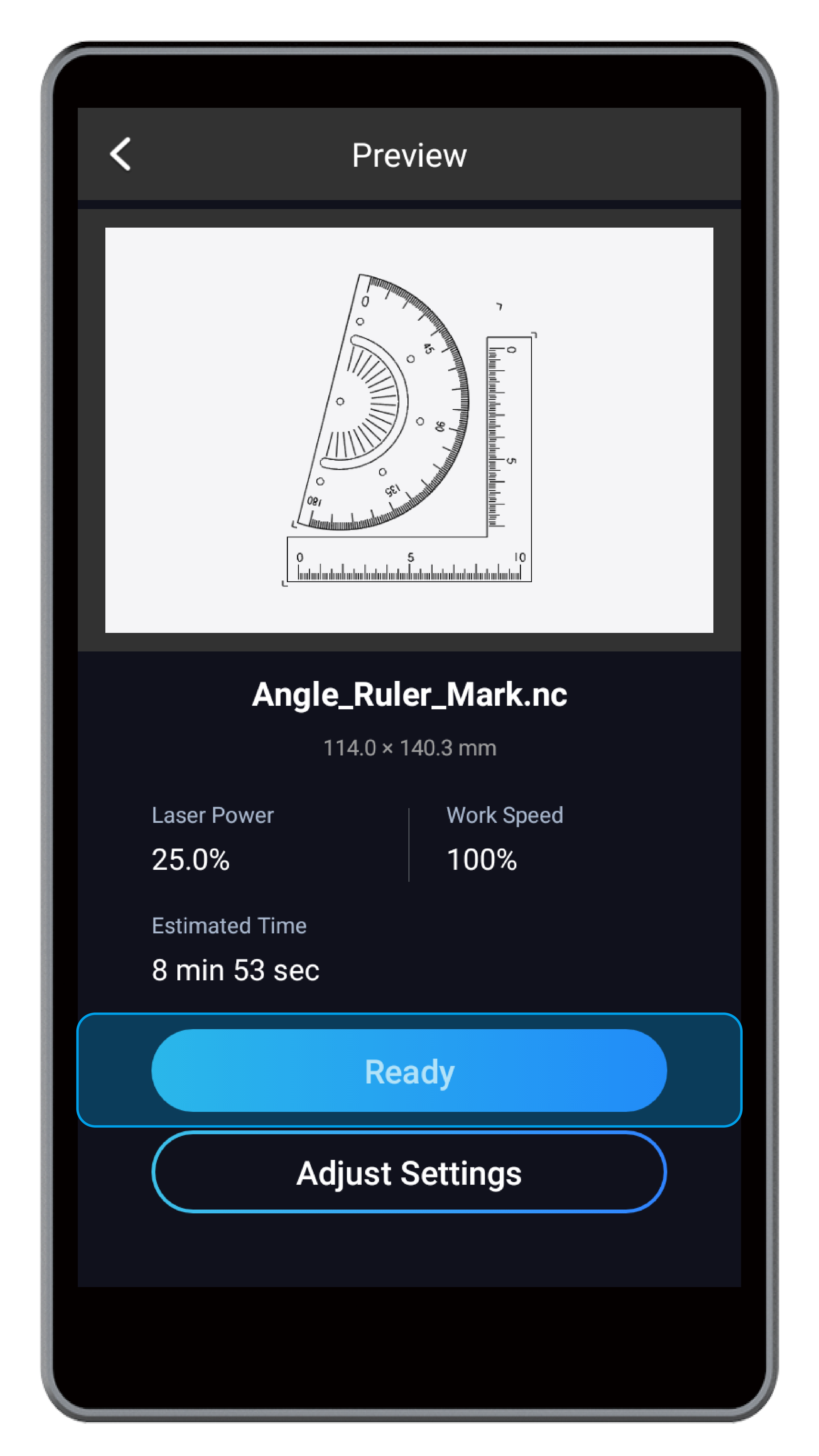
![]() You can tap Adjust Settings to modify Laser Power and Work Speed.
You can tap Adjust Settings to modify Laser Power and Work Speed.
(4) On the Select Mode screen, select Auto Mode or Manual Mode. If you select Auto Mode, the machine will measure the material thickness and do automatic focusing. If you select Manual Mode, you need to manually control the toolhead to touch the material surface. Then, the machine will do automatic focusing.
- Auto Mode
Tap Auto Mode > read Note for Auto Mode > click Start to enter the material thickness measurement process:
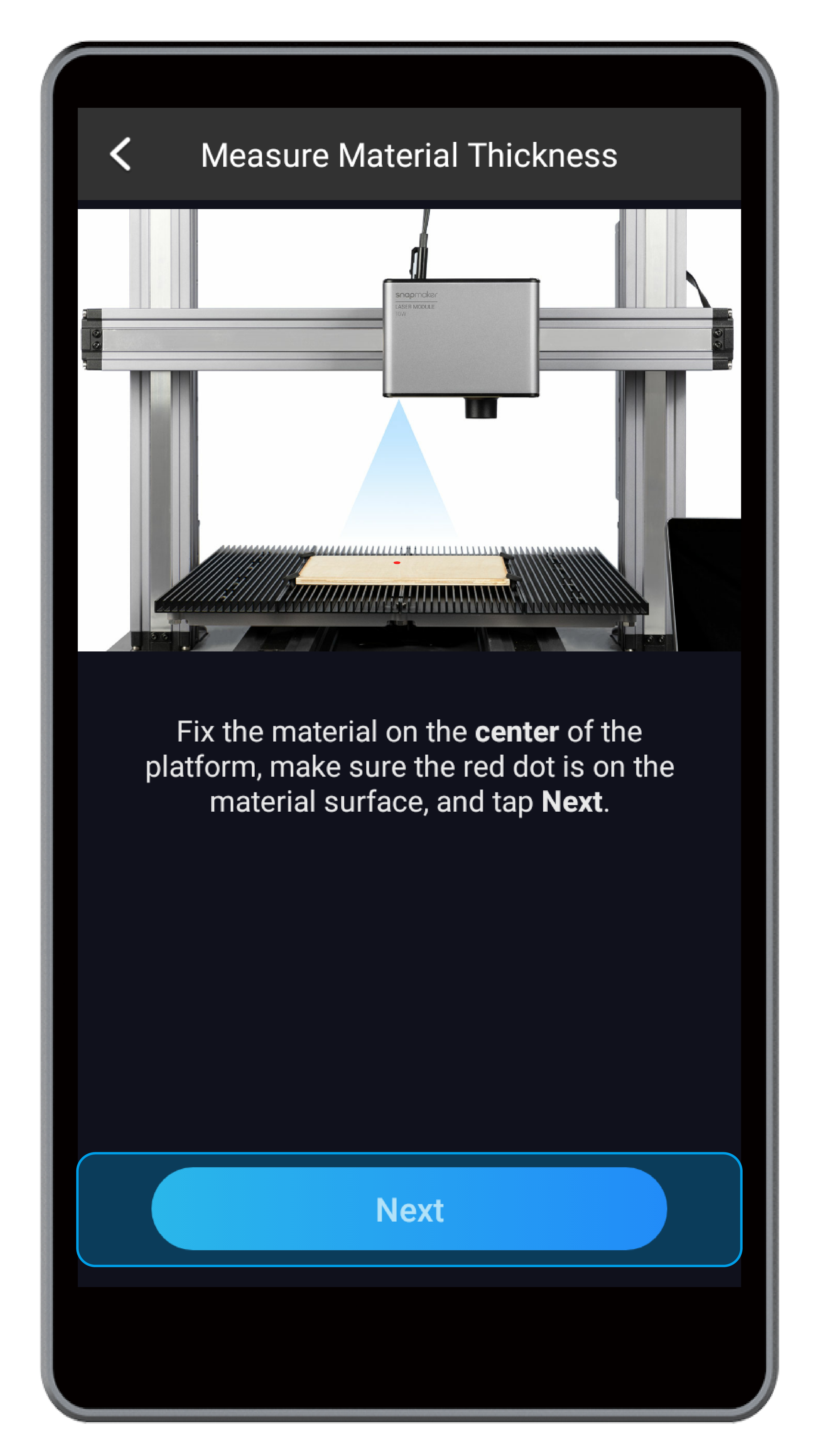
- Ensure that the red dot falls on the material surface.
- Tap Next, and the machine will measure the material thickness.
- After confirming the measuring result, tap Next, and the machine will do automatic focusing.
![]() If one of the following conditions happens, thickness measurement may fail:
If one of the following conditions happens, thickness measurement may fail:
-
- The material thickness is over 50 mm.
- The material texture is transparent, or the material surface is glossy or specular.
- The material color is red or black.
- The environment is too bright.
If the thickness measurement fails, you can switch to Manual Mode.
- Manual Mode
Tap Manual Mode > read Note for Manual Mode > tap Start to enter the Touch Material process:
- Tap X-/X+/Y-/Y+ to move the toolhead over the material.
- Place the calibration card or a piece of A4 paper between the 10W Laser Module and the material. Keep adjusting the Z Offset until you feel slight resistance when you pull out the calibration card, and it should be wrinkled when you push it forward.
- Tap Next, and the machine will do automatic focusing.

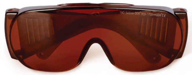
(5) Ensure that all the operators and bystanders have correctly put on the laser safety goggles. Then, tap Next.
(6) Tap X-/X+/Y-/Y+ to move the laser dot to where the work origin will be, and tap Set Work Origin. Then, tap Run Boundary to check if the work area is proper. If not, repeat this step until you set a proper work origin.
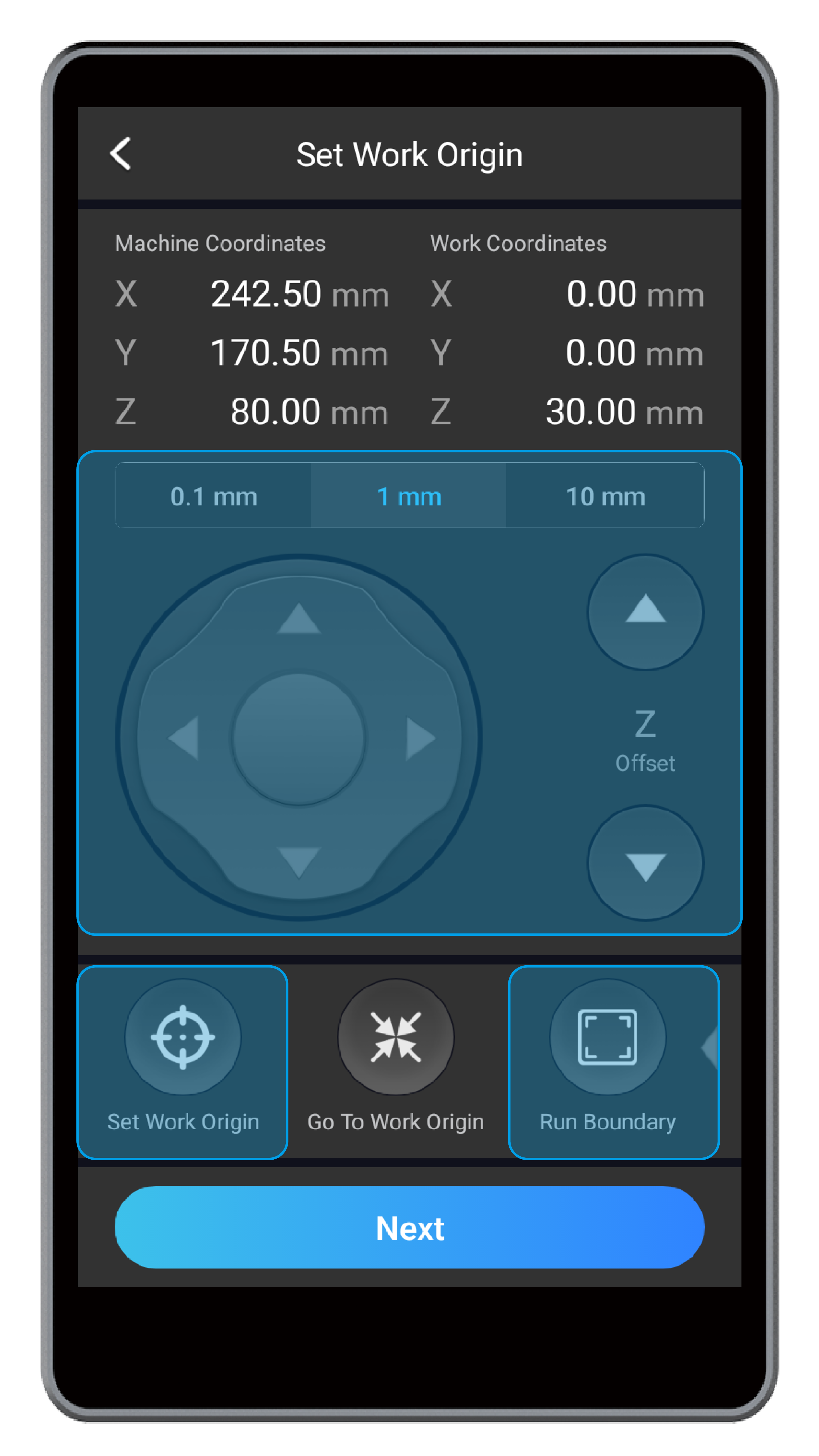
![]() If the laser beam runs out of the laser engraving and cutting platform, or the air concentrator hood bumps into the machine, turn off the machine immediately or press the Emergency Stop Button
If the laser beam runs out of the laser engraving and cutting platform, or the air concentrator hood bumps into the machine, turn off the machine immediately or press the Emergency Stop Button ![]() .
.
(7) Close the Enclosure and click Next to start laser engraving and cutting.
![]() If you use the 10W Laser Module for continual cutting at 100% laser power for more than eight hours, its service life may be shortened.
If you use the 10W Laser Module for continual cutting at 100% laser power for more than eight hours, its service life may be shortened.
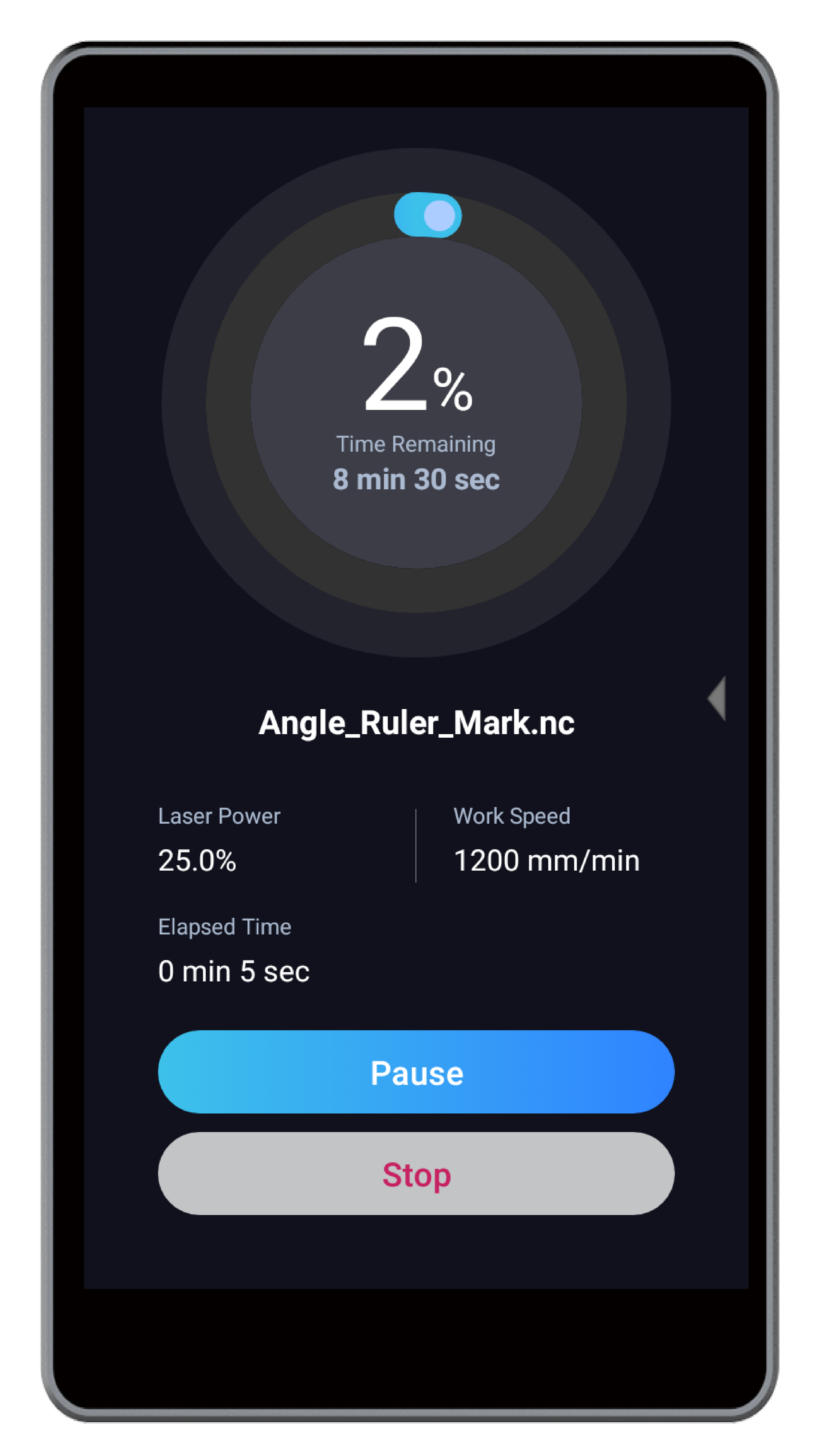
![]() During laser engraving and cutting, you can perform the following operations:
During laser engraving and cutting, you can perform the following operations:
- Swipe left on the Touchscreen to modify Laser Power and Work Speed.
- Tap Pause to pause the ongoing laser job, and tap Resume to continue.
- Tap Stop to stop the ongoing laser job. If you stop a job, the job cannot be resumed.
Start Engraving and Cutting on Luban
(1) Connect your machine to Luban (see 3.5 Connect the Machine to Luban).
(2) Load the G-code file to Workspace.
- If you generate the G-code file on Luban, click Load G-code to Workspace to load the generated G-code file to Workspace.
- If you want to use a G-code file stored in your computer, click Import on the G-code Files panel of the Workspace. Select a G-code file (in nc. format) from your computer and click Open.
(3) Ensure that all the operators and bystanders have correctly put on the laser safety goggles. Then, on the left Laser panel of the Workspace, turn on Laser Power.
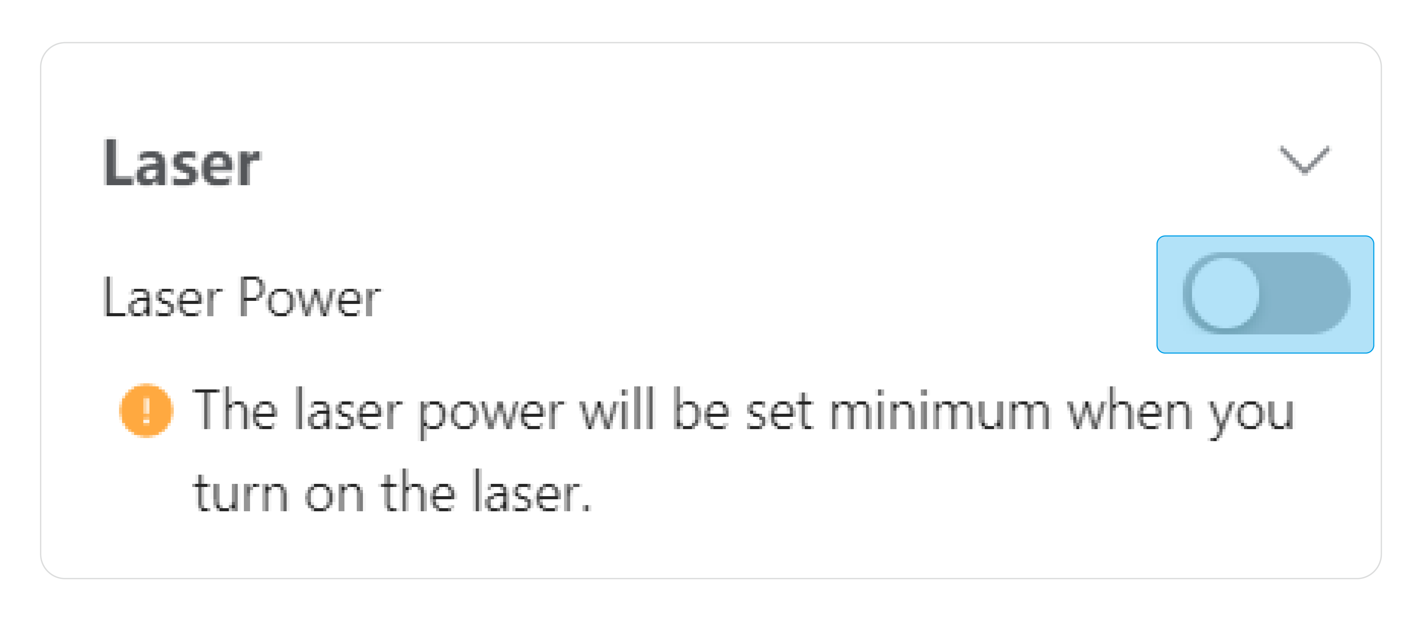
(4) On the right Control panel of the Workspace, set Work Origin.
(a) Click X-/X+/Y-/Y+/Z-/Z+ to move the toolhead until you can see a clear laser spot on the material surface.
(b) Click X-/X+/Y-/Y+ to move the laser dot to where the work origin will be, and click Set Work Origin. Then, click Run Boundary to check if the work area is proper. If not, repeat this step until you set a proper work origin.
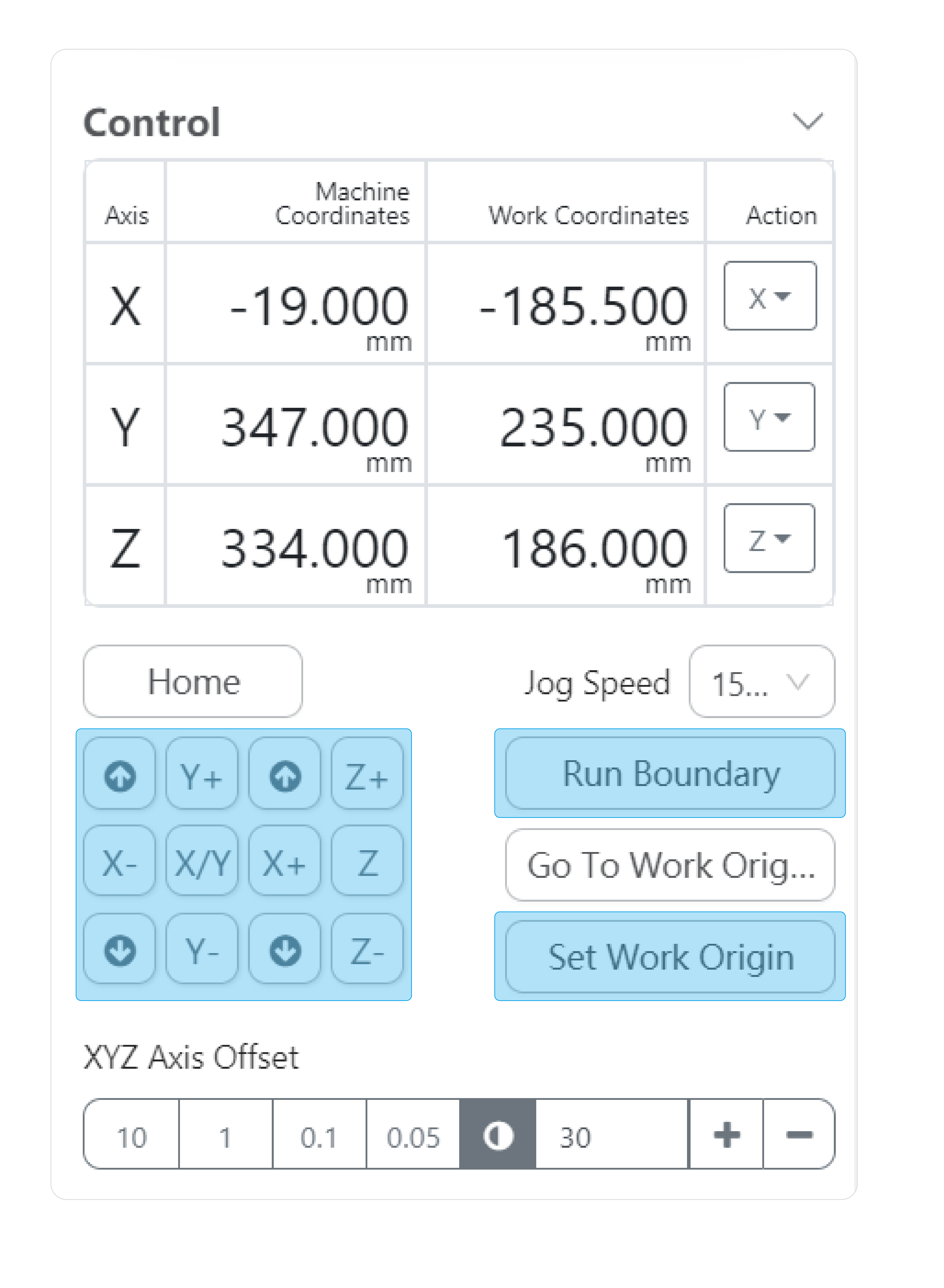
![]() If you use the Camera Capture method to determine the position of the object, skip this step to continue the following operations.
If you use the Camera Capture method to determine the position of the object, skip this step to continue the following operations.
(5) Close the Enclosure.
(6) On the G-code Files panel, select the prepared G-code file and click Start on Luban. On the pop-up Start Job window, you can select Auto Mode, and the machine will measure the material thickness. Alternatively, you can unselect Auto Mode to manually input the material thickness.
- Auto Mode
On the pop-up Start Job window, tick Auto Mode. Then, click Start, and the machine will measure the material thickness, do automatic focusing, and start laser engraving and cutting.
![]() If one of the following conditions happens, thickness measurement may fail:
If one of the following conditions happens, thickness measurement may fail:
-
- The material thickness is over 50 mm.
- The material texture is transparent, or the material surface is glossy or specular.
- The material color is red or black.
- The environment is too bright.
If the thickness measurement fails, you can switch to Manual Mode.
- Manual Mode
On the pop-up Start Job window, untick Auto Mode to enter the Manual Mode. Input the material thickness. Then, tap Start, and the machine will do automatic focusing and start laser engraving and cutting.
![]() If you use the 10W Laser Module for continual cutting at 100% laser power for more than eight hours, its service life may be shortened.
If you use the 10W Laser Module for continual cutting at 100% laser power for more than eight hours, its service life may be shortened.
![]() During laser engraving and cutting, you can perform the following operations:
During laser engraving and cutting, you can perform the following operations:
- On the left Laser panel, modify Laser Power and Work Speed: input new values and click the Refresh button .
- On the right Job Status panel, click Pause to pause the ongoing laser job, and click Run to continue.
- On the right Job Status panel, click Stop to stop the ongoing laser job. If you stop a job, the job cannot be resumed.
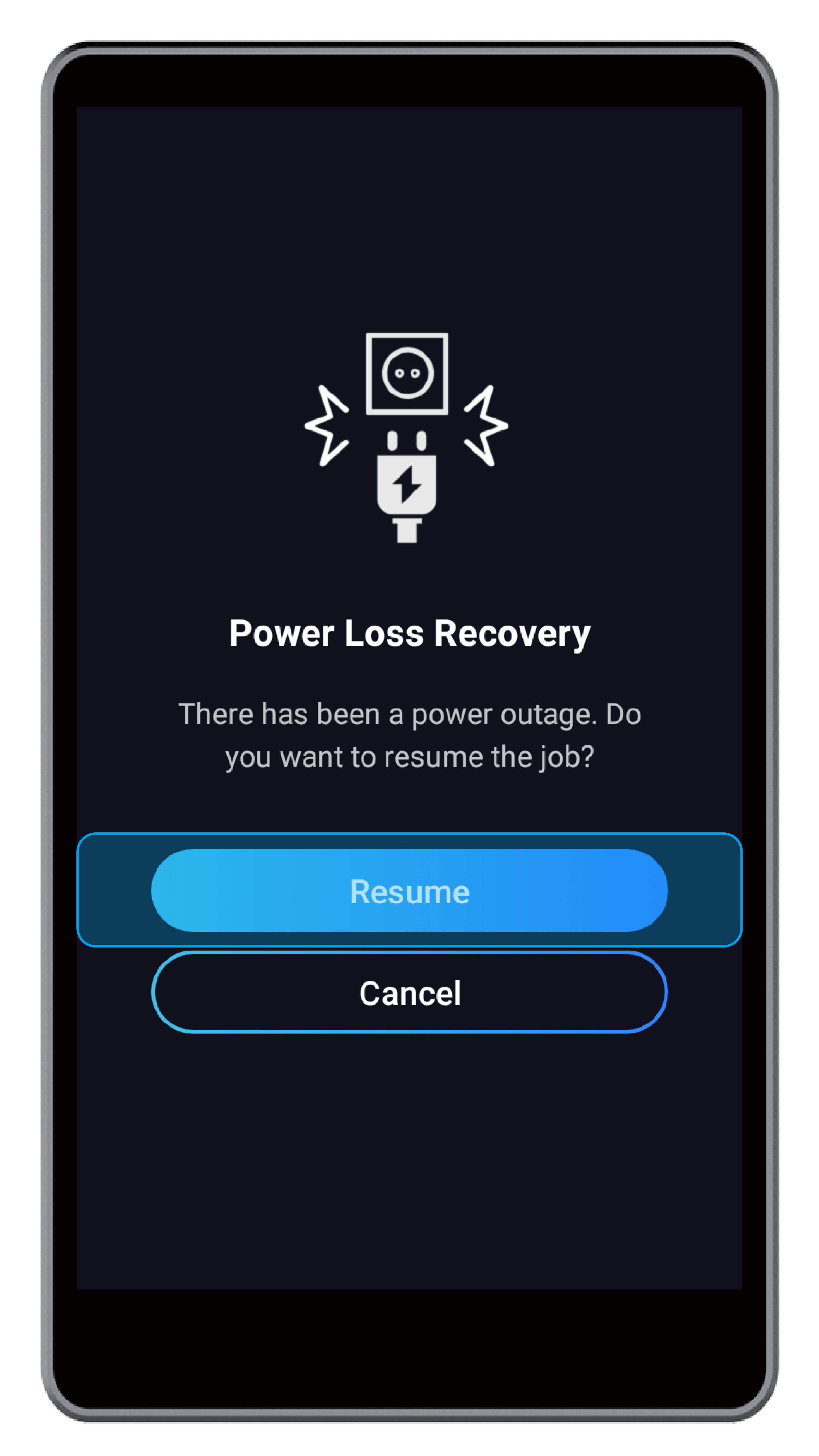
3.9 Power Loss Recovery
This feature enables you to restart a laser engraving and cutting job from where you left when a power loss occurs. If the Power Module is turned off or the AC power cable is unplugged during laser engraving and cutting, you can take the following steps to resume the job.
(1) Restart the machine.
- If the power loss occurs for the Power Module is turned off, you can turn on the Power Module to restart the machine.
- If the power loss occurs for the AC power cable is unplugged, you must turn off the Power Module before you reconnect the AC power cable. After you confirm that all cables are correctly connected, turn on the Power Module to restart the machine.
(2) On the Touchscreen, tap Resume, and the machine will continue the last laser job.
Power Loss Recovery applies to only laser engraving and cutting jobs that are started on the Touchscreen.
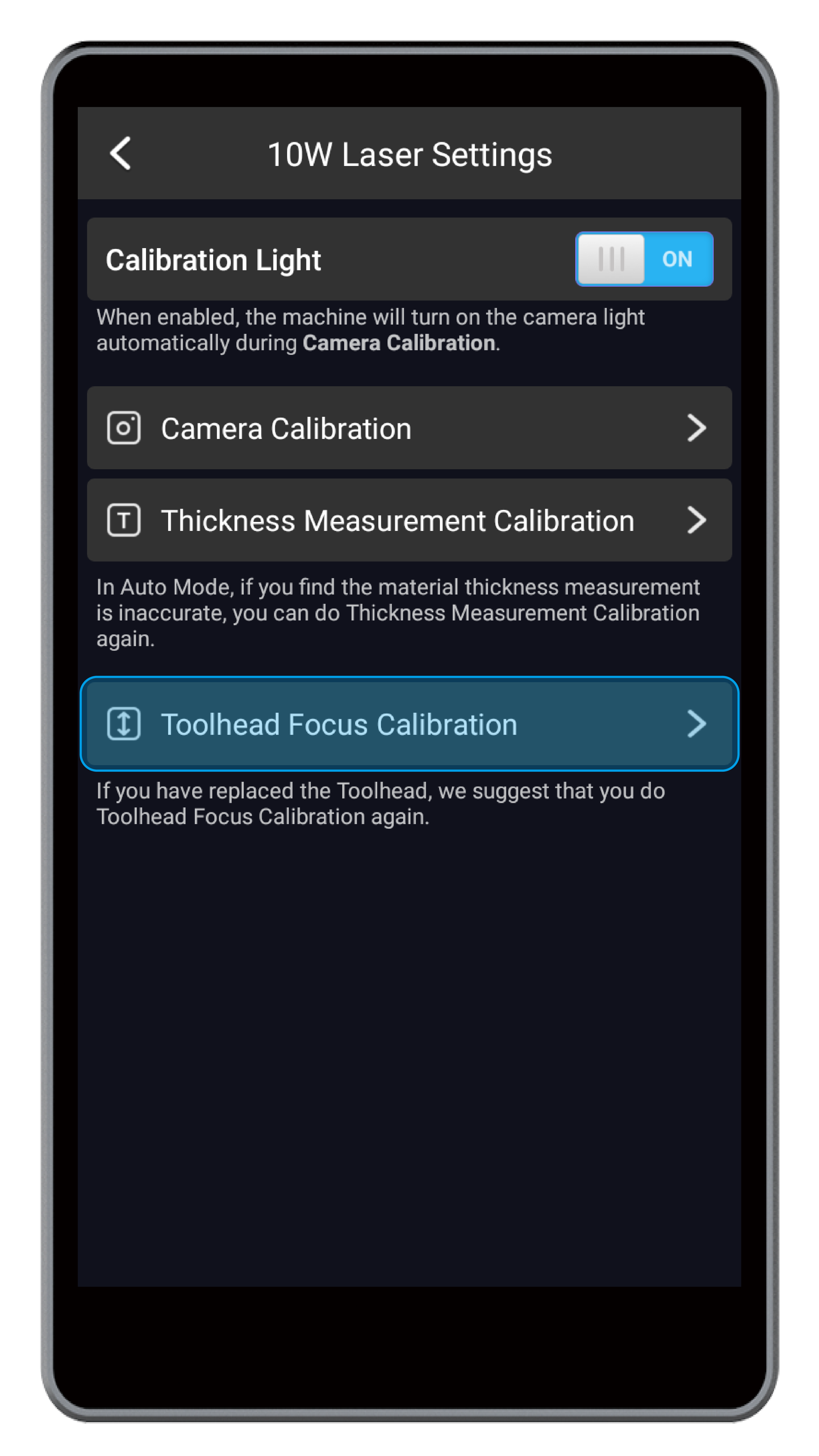
3.10 Enable or Disable the Calibration Light
Calibration Light is enabled by default. When you calibrate the camera, the machine will turn on the camera light for illumination.
You can disable Calibration Light: swipe left on the Home Screen of the Touchscreen, tap Settings > tap 10W Laser > turn off Calibration Light.